[post deleted per user request]
Skip to main content
I get the same problem with the print head sliding to the left and the bad vibration/drilling noise which I was told by the IT geeks to send photos or a video,not sure what a photo will do lol .My reply to that was even if I did send a video it still won’t fix the software problem .I got a reply today saying they are updating the software soon and they will let me know soon
Hi I have just completed my 3d printer from Eaglemoss It was hard to calibrate but found best to use a larger object rather than the 02mm gauge say 75mm high with the build plate at a lower level then when level raise the plate until reaching the 02mm gap This made it much better to level the plate the only problem I have is the bed plate will not heat I have resolved this problem by getting PLA from Rigid ink. I now get very good results as Rigid ink PLA will stick to a cold bed.
I would add that getting the bed plate level and at the right distance from the extrude is very hard.
Hi i had the same problem but then found i had fitted the brackets on the wrong side instead of between the fan and block this raised the fan blower but the clearance is very small and i did need to bend the brackets a little but all works fine now
Guys I think this is due to the limit switch not being pushed in fully when it moves to the egde
Is anyone having any problems with grub screws coming loose after a few prints? which then causes the printing to go out of line and I wondered if anyone had any solutions for that? I am thinking metal glue
.
[post deleted per user request]
Well i have fixed it by removing the bottom screw of the plastic plate/grip that holds the limit switch in place. Pushinh it as far right as possible and glueing it in place. Its just because its about 1mm out. You can test it by moving the x-axis left and right to make sure the limit switch clicks when it reaches the end
Ive found you can buy grub screws online woth threaded locks to stop them coming undone with vibrations. Im guna give that ago if not threaded lock glue seems the way
I think this is what we are looking for. I have ordered some so I will soon find out.
Still having trouble with the printer and software,the damn thing still vibrates as the printer head tries to go further to the left than its supposed to and the software still doesn’t tall to the printer so nothing prints.I have emailed both the tech guys and Eaglemoss with very little in the way of a solution and I also tried calling both the v3 customer services and technical help and was on hold for 10 minutes on each so I gave up. A refund is what I want now as it’s turned what I thought would be a good project and product into a large paperweight.Rant over
[post deleted per user request]
Graham, the problem with the damn thing still vibrates as the printer head tries to go further to the left than its supposed to is a problem with the limit switch not being being pressed in fully, I put my fix below. You need to make sure it fully clicks as the print nozzle arm inside the metal case pushes the limit switch down.
If it is fully clicking and being hit every time and not being pushed back away then you will have a problem with the limit switch but either way thats what the limit switch is for and that is the reason, it is there to say " this is the end, stop moving in this direction "
Hi All
I know that some of us are having issues with this printer, however if you do manage to get it to work here are some tips.
Firstly forget the slicing system in the printers software just use it as a way to connect to your printer, send the g_codes.
download
Meshmixer at www.meshmixer.com
Slic3r at http://slic3r.org
Meshlab at http://meshlab.sourceforge.net
Now I use Meshmixer to add the support structure to the Model, Slic3r to generate the g_code then upload with 3d create and print.
now Meshlab I use to convert the sketchup file to stl as sometimes the sketchup plugin fails.
Here are the settings for PLA in Slic3r I use which seem to work.
In Print Settings
Layers & Perimeters
Layer Height 0.2
First layer Height 0.2
Perimeter 3
Solid layers top and bottom 3
Seam position random
Infill
Fill density between 25% and 80% depending how strong you want the Model
Fill Pattern Honeycomb
Top & Bottom Fill pattern Rectilinear
Combine every fill layer 1
Only when needed tick
Solid infill layer 3
Fill angle 45 degrees
Solid infill threshold 70 mm2
Infill before perimeter tick
Skirt And Brim
Loops 4
Distance from object 4
Skirt height 1
Minimum Extrusion length 0
Brim width 0
Support Material
Make sure it is not ticked as you will get better results from Meshmix do look on youtube for tutorials.
Speed
Perimeters 30
Small Perimeters 20
External Perimeters 15
Infill 50
Solid Infill 50
Top Solid Infill 50
Support Material 50
Support Material Interface 60
Bridges 60
Gap Fill 20
Travel 80
First Layer Speed 30
The rest of the settings make sure they are set to 0 except Max Print Speed set to 80
Multiple Extruders
Make sure the settings are set to 1 and the tick boxes are empty
Advanced
Make sure all settings are set to 0 except these settings
First Layer 200%
Infill Perimeter Overlap 20%
Bridge Flow Ratio 1
Threads 2
That’s all the setting for this section
Filament Settings
You need to set that according to the material you are using and the recommended settings**.**
Printer Settings
General
Bed Shape Rectangular
Size 140 X 140
Origin 0 0
Extruders 1
G-Code Flavor RepRap
Pressure Advance 0
Vibration Limit 0
Custom G Codes leave alone
Extruder 1
Nozzel Diameter 0.4
Extruder Offset 0 & 0
Length 1.5
Lift Z 0.5
Speed 20
Extra Length On Restart 0
Minimum travel after retraction 1.5
The two boxes not ticked
Length 10
Extra length on restart 0
This should set you up for printing
When you do load the G-code the printer will tell you the bed is heating , But it will not mention the print head. Just let it run.
Now as for the Printer
That square PCB build plate get shot of it as it is useless.
Get hold of some sheet Aluminum the same size as the PCB. Rough the surface with some 80 grit emery paper.
When you get ready to to print spray the Aluminum with cheap Hair Spray, this will help combat warping.
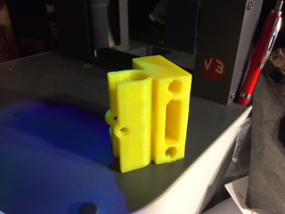
I have added a Photo of the results.
Do search for tutorials on the software packages I have mentioned, but ultimately get a better printer for half the price we had to pay for this thing.
And guess what you can print with it ad the printer works to build cases to cover the electronics.
No sarcasm intended I done the same within two days of firing this v3 up
I have not been able to connect with the printer using repetier.
[post deleted per user request]
Yes please
Do any of you guys think the bed mount points need to be stronger ?
Thankyou
Will be glad to move away from the V3 Just rebuilding my Prusa I3 onto a 3mm Steel Frame.
Then I will Probably donate this V3 to My child’s School where Precision is not an issue.
I’m ever the optimist…
I had one great print from this printer two days ago, and I thought I had cracked it.
Mmmm not the case how wrong could I have been as the next few prints started to degrade, and I thought it was my settings.
Tonight I started a print to discover the bed was not positioning to where I had calibrated it so I went through the process again, and found it was significantly off.
After closer inspection of the z axis I found that it alters its position, and this is due to the flimsy construction. I should not be able to move the axis by hand by 10mm. No wonder every photo of prints show visible ghosting.
I do not know what the answer is for this one I think I shall have to either gut it for parts or use it as a door stop, but I cannot risk the print quality
I must be one of the lucky ones my printer is working fine even the software from Eaglemoss is working OK the only problem I have is the bed will not heat but with the use of masking tape and Ridge Ink PLA sticks to the bed well.
I did fine the calibration was hard and took some time but the bed has not moved and is still working after a number of prints.I also had a problem with the extra fan as the vent part did catch on the bed plate when first fitted but a small amount of bending the holding brackets solved this.
I did find that if I printed a large circle 125 dia and 1mm deep helped with the calibration as it was better to seen any errors.
I’m still emailing the technical staff about the problem with the extra fan and nozzle from issue 91. I too found it fouled the clip on the build plate and could catch. Also it was over cooling the print head so it never quite reached temperature. I’ve butchered the nozzle by cutting about 3mm from the nose, and altering the cut outs for the screws so that it sits flatter to the assembly. Lastly I have taped over 50% of the nozzle to restrict the cooling effect. None of that should be necessary though, and the latest emails suggest reversing the “silver brackets” and that there is a mismatch between the software temperature setting and the heater. They suggested turning up the software setting but that is odd as if the head doesn’t reach whatever is set then the printer won’t commence. My first print was a disaster and I had to clear a blocked print nozzle. The calibration setting is a real headache. I can’t understand how the V3 can have been around for this long yet there aren’t proper solutions. Oh, and the Mac software won’t open, it just crashes. Good job I have Windows too. Stephen
They will help, however I would also go into manual mode and check that all axis move smoothly. I have found that my z axix is all over the place, and on closer inspection the weight of the x axis is causing the z axis to twist.