


For some time now I have wanted to 3D Print a quadcopter. So I have started and wanted to share the project with you guys. Maybe some of you are in the same situation, Maybe you don’t know anything about quads but a lot about 3d printing and want to start this fantastic hobby. Then I invite you to join this build. Or if you just have questions, think I could have done something different or made some fatal mistake that I need to know about before I crash this thing. You can also join to help me build this tutorial, let me know if you have changes or suggestions.
Preparation**:**
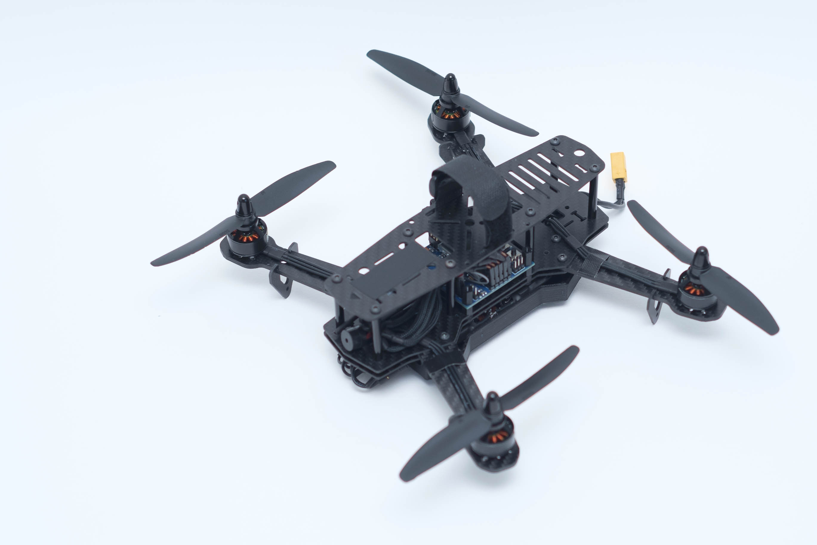
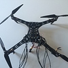
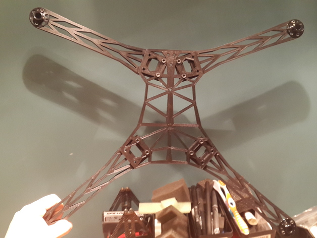
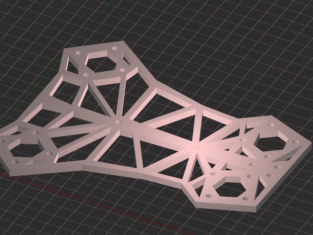
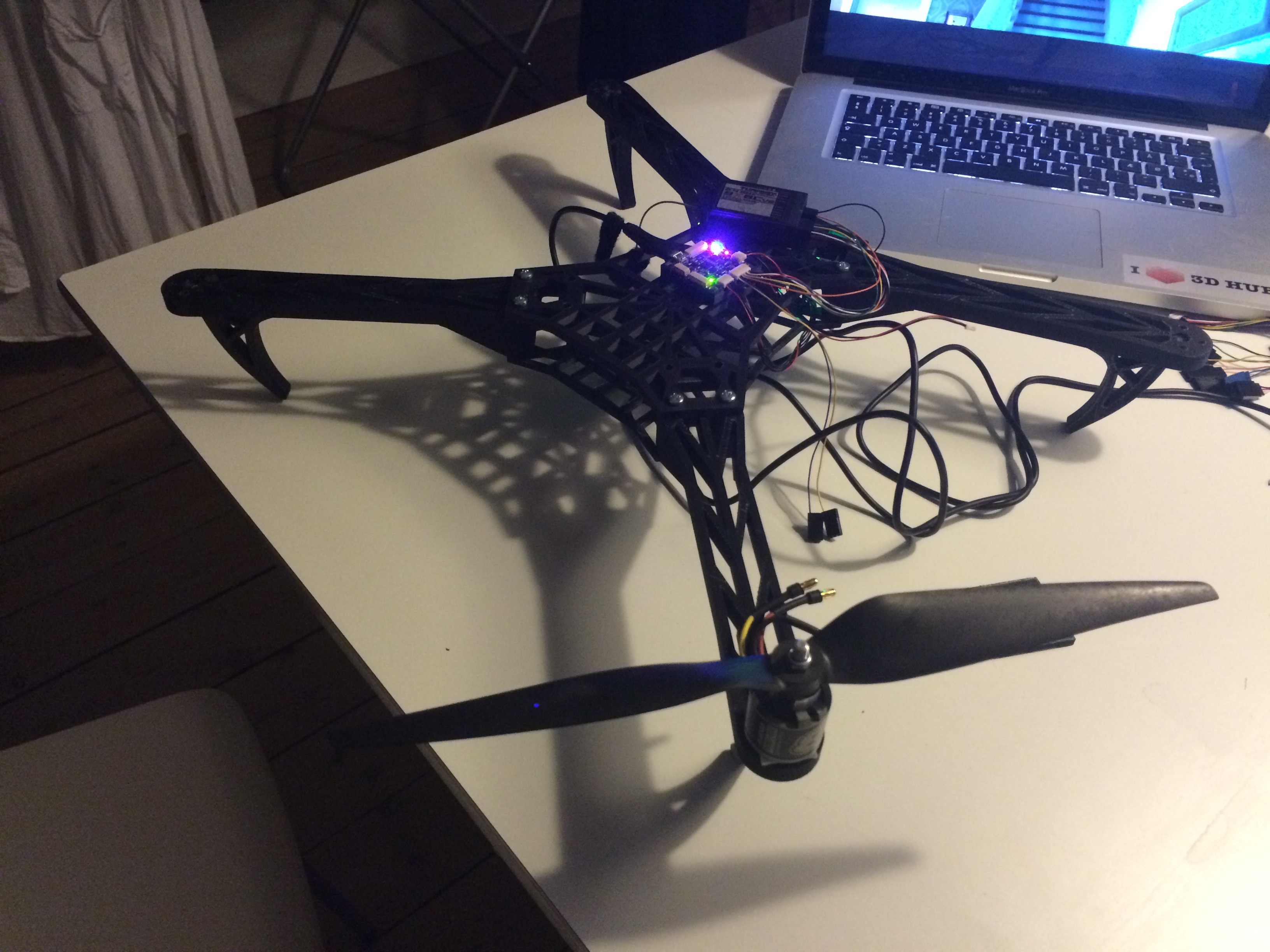
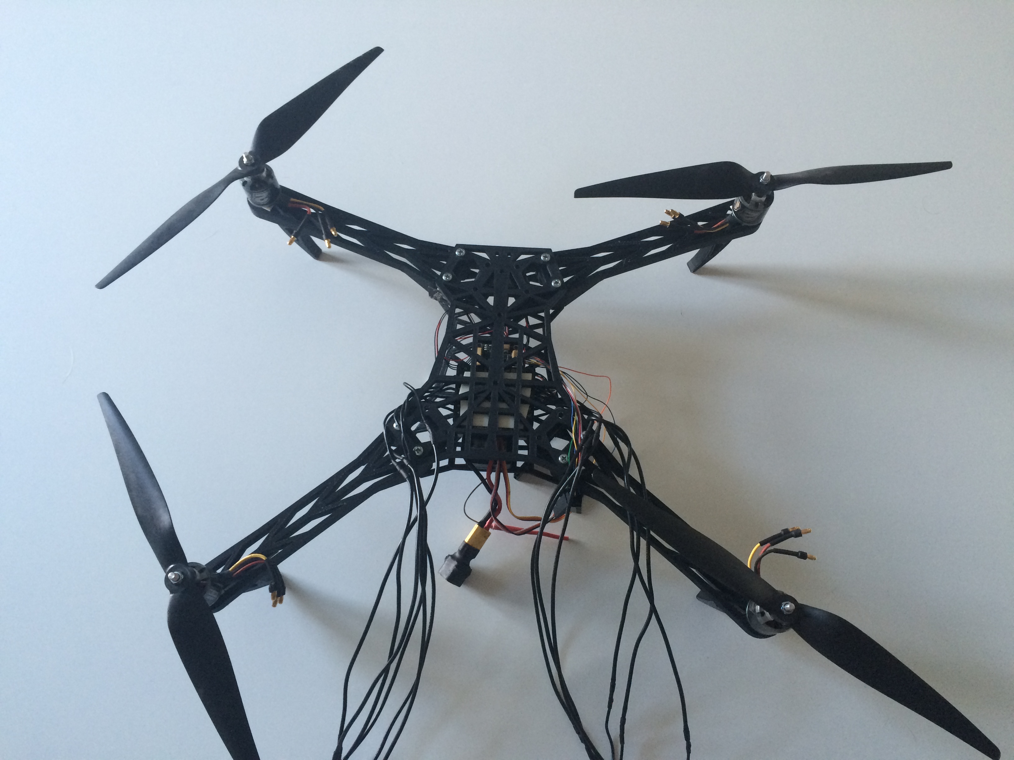
First off we need to chose a frame based on what you want to do. I want to build a fpv quadcopter with the possibility to add some mapping functions later on. I like the spyda frames (500) so I went with this one from 57Thingiverse 57.
I had to modify the arms to fit my motors.
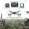
And then we need chose the electronics and props.
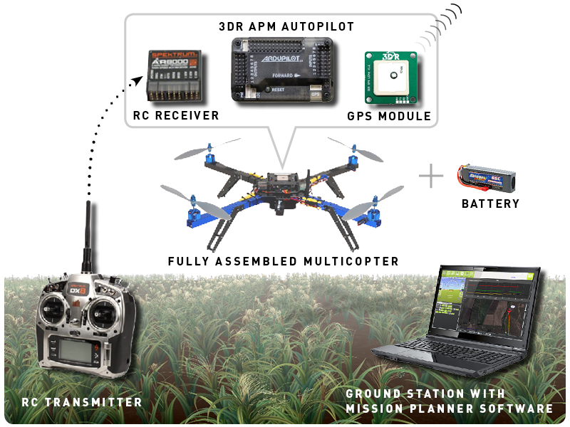
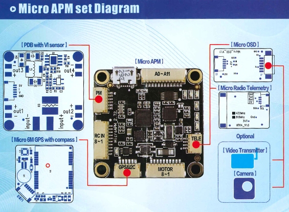
- Flight controller: HKPilot mega micro kit with GPS, OSD and telemetry 433MHz
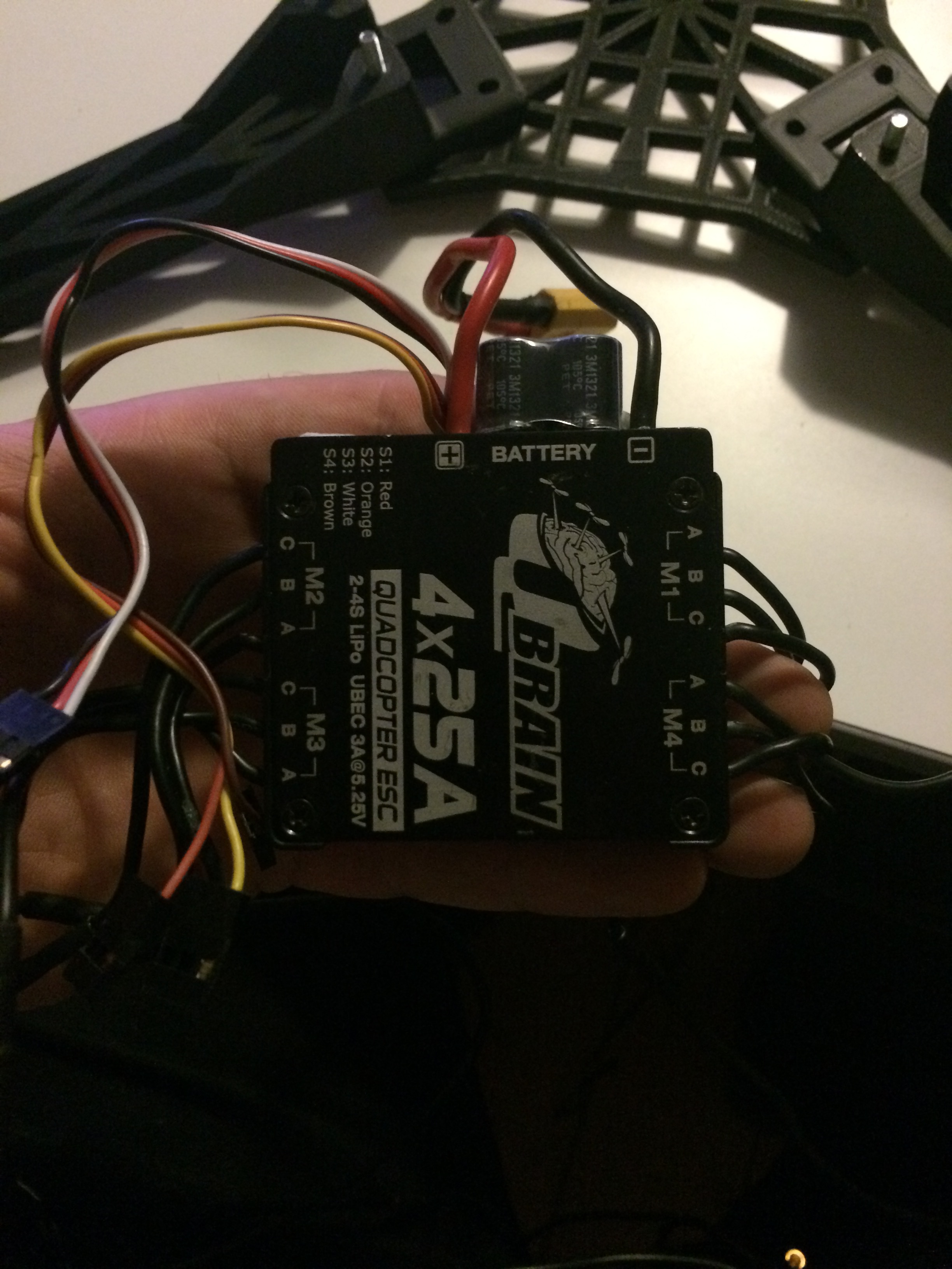
- ESC: Q Brain 4 x 25A Brushless Quadcopter ESC 2-4S 3A SBEC
- Motors: NTM Prop Drive 28-30S 800KV / 300W Brushless Motor (short shaft version)
- Props: 11x4.5
- Battery: Turnigy nano-tech 4500mah 4S 45~90C Lipo Pack
These parts come from a different quad build i had sitting around.
Software you will need:
- Mission planner from 3DR.com 12
Day one to six - printing all the parts:
The printing went as I expected. Only problem was the pcb extruder board on the Zortrax M200 broke. So took some time getting a new one.
As for print settings go, I used the Zortrax M200 with ABS so not much to tell here.
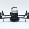
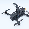
All the parts look and feel strong, so perfect, so far.
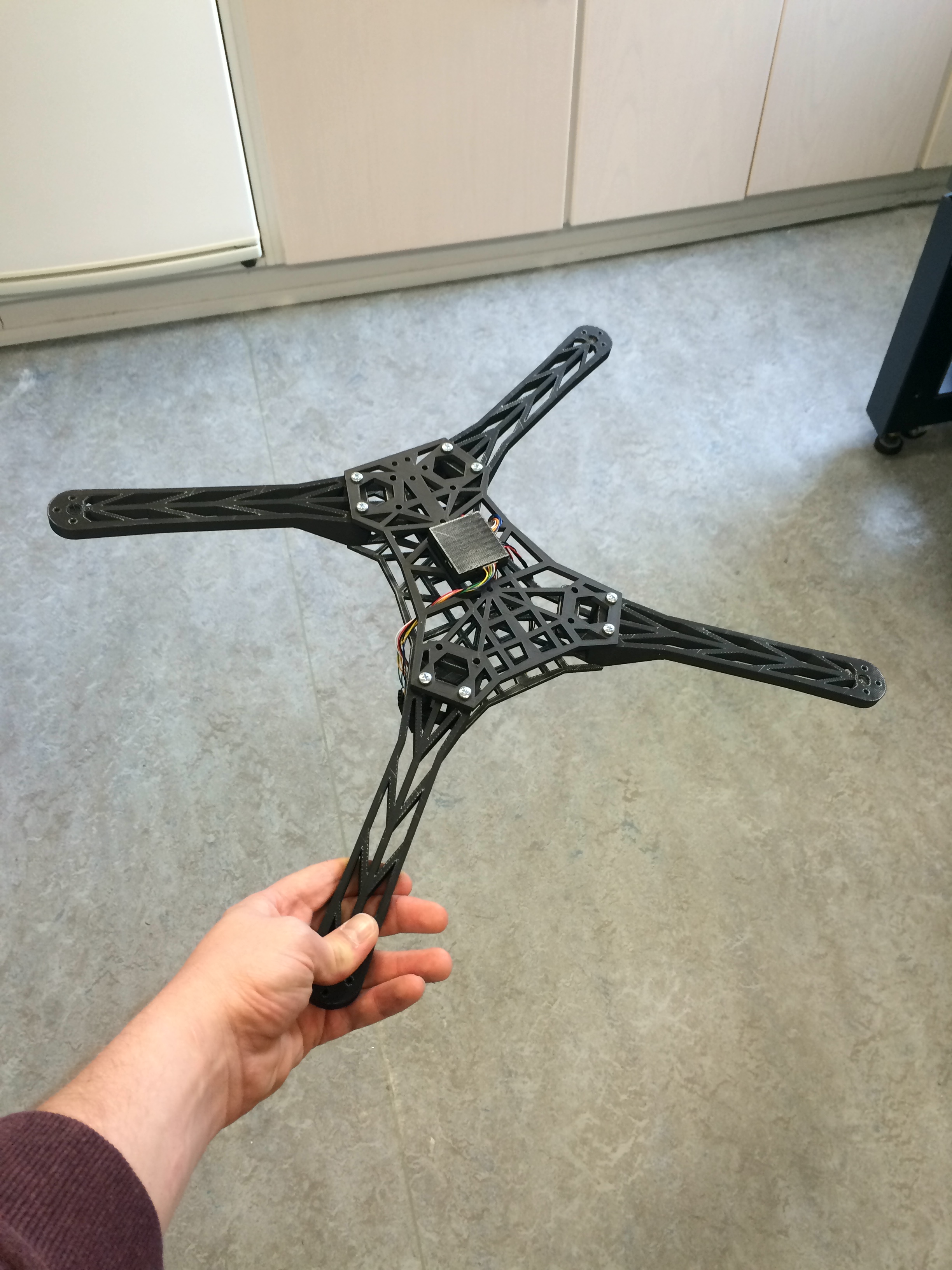
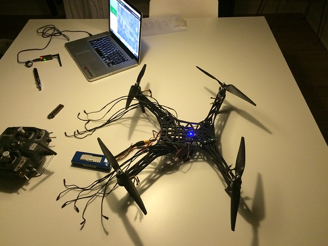
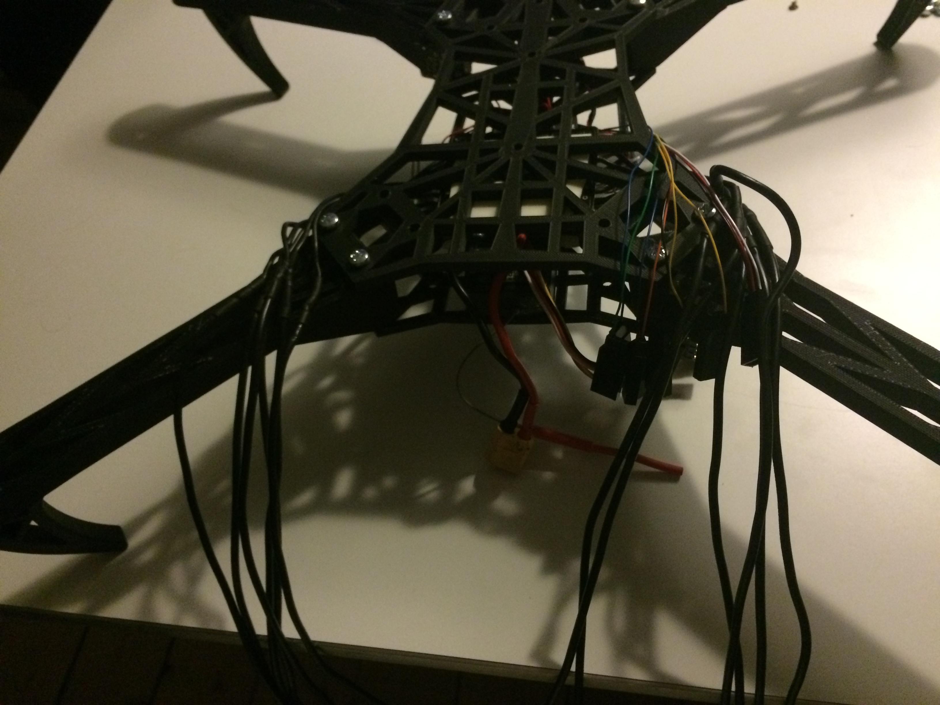
Day 7 to 8 - Putting all the electronics together and building a case for the mini apm.
So now comes the hard part.
I started off testing the apm with mission planner to set up frame type. I chose v-tail for my dead cat frame. It might change later on as I get flying.
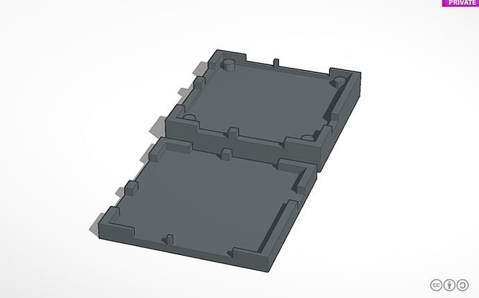
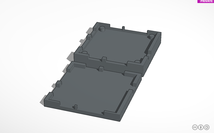
I had to design a case for the apm, as I have experienced with a different build that light and airflow will effect the barometer on the board and loiter will be impossible. Design was made in tinkercad.
Next up was wiring up the receiver to the apm with all the small cables. It was a lot more simple than I expected. RC IN 1 is right after 5V red and GND black and then 2 3 4 5 6 7 follows. This is as far as I know different from tx/rx system to tx/rx system. And I know you can use PPM as well, maybe some one here can explain that.
Now for connecting the 4i1 esc. Same as with the receiver. Red, black and signal wires 1 2 3 4 5 6 7 8. And since this is a quad we will only be using the first four signal wires, the rest we can remove to loose some weight.
Now we add the telemetry, osd and gps module.
There is a y cable for the telemetry and osd modules and a normal cable for the gps. As long as you stick to the wiring diagram you cant go to wrong.
Day 9 - Mounting the motors.
I did something wrong in tinkercad when I modified the motor holes in the arms. So I will have to make a drill jig to fix that.

Update will follow. Soon.
created
Feb '15last reply
Dec '15- 13
replies
- 9.5k
views
- 7
users
- 16
likes
- 10
links