I recently got an Anet A8/Prusia i3 which, when delivered, was missing the cabling for the heatbed - so I figured on upgrading the cabling whilst I’m at making a new lead up.
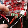
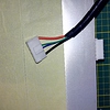
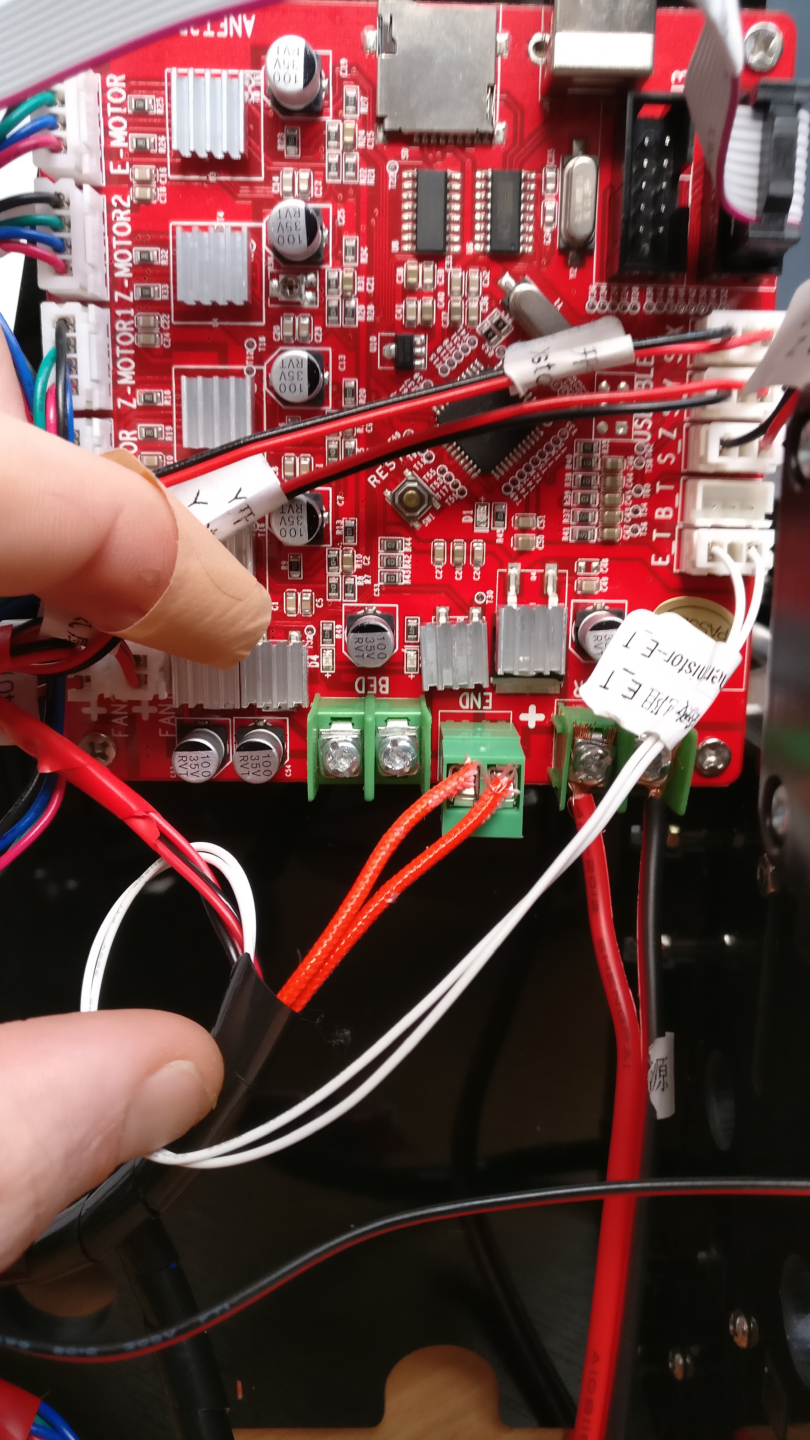
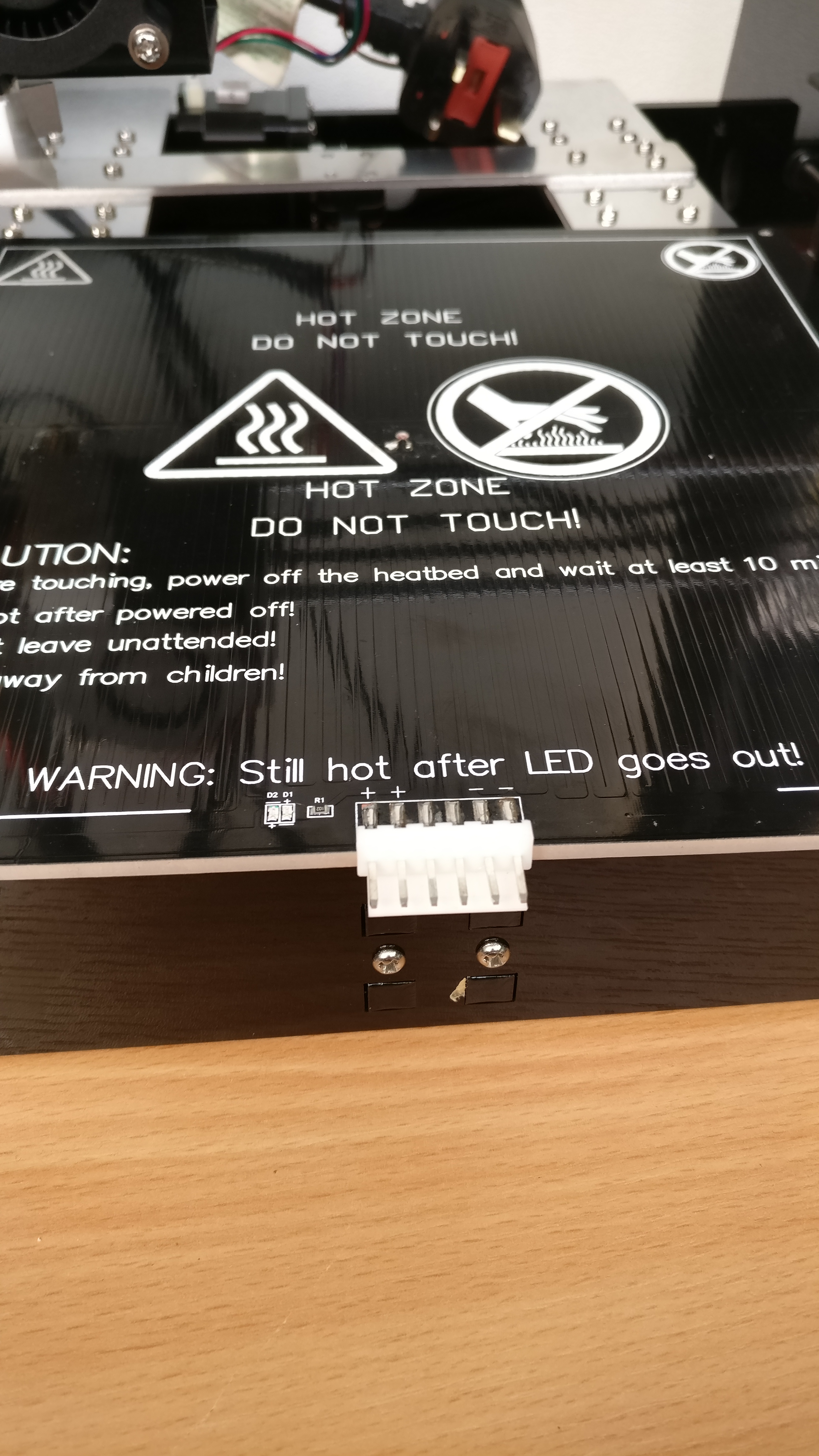
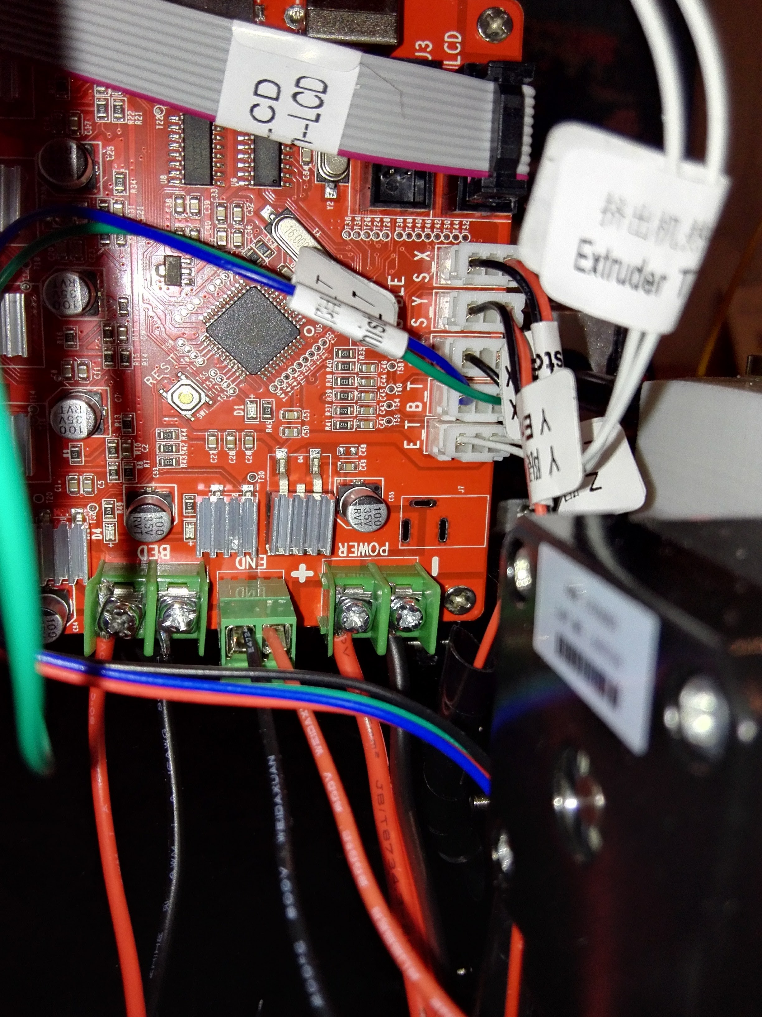
The connections look like standard 3 & 6 pin JST Connectors - Can anyone who has the same printer show me where the wires lead off to for the heatbed? i.e where the B_T & BED leads go in the ++ – 6 pin connector?
The connector in my photo is the unmodified, original version, but I’m going to replace it with a MOSFET module. This is highly recommended to prevent overheating the wires and/or other parts of the printer. The standard connector and wiring set is not designed to handle large amounts of current. It’s a design flaw from Anet that should have been fixed.
Learn more about this here: https://3dprint.wiki/reprap/electronics/heatbed_mosfet 241
If you’re not going to use a MOSFET module, I recommend that you connect the red wire to both + terminals on the heated bed and the black wire to both - terminals. This way the current is distributed more evenly.