Injection Molding - Undercuts (How to Avoid and Design)
Thanks for tuning in to our series: “Designing for Injection Molding”. In each episode of this series, we’ll be discussing a different design feature encountered in injection molding. Today, let’s talk about undercuts.
We’ll discuss what an undercut is, how to deal with undercuts, and finally, we’ll demonstrate in Fusion360 how to design a part with undercuts in mind. Before we get started though, download our free guide on designing for injection molding.
So, what is an undercut?
An undercut is a feature that can make it difficult for a part to be ejected from the mold. It’s a part feature that cannot be manufactured with a simple two-part mold, because material is in the way while the mold opens or during ejection. Power switch slots, teeth of a thread, and locking tabs are examples of undercuts. Unless your design really needs undercuts, try to avoid them. Special tooling can be used to correctly eject the part from the mold when you have an undercut, but this adds to the cost and overall time of your project.
When designing your IM part and avoiding undercuts, there are 4 main ways to do this: using shutoffs, moving the parting line, bumpoffs, and sliding side-actions and cores.
Shutoffs
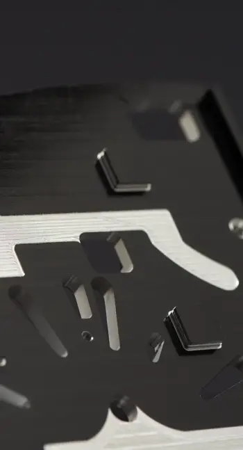
Shut-offs are a useful trick to deal with undercuts on internal regions of the part for snap-fits or on the sides of the part for holes or handles.
A shut-off is a piece of metal sticking out from the core side of the mold to produce an overhang without a side action. It produces the underside of the cantilever/hook. Essentially, the material is removed in the area under the undercut, eliminating the issue altogether
Moving the parting line
The simplest way to deal with an undercut is to move the parting line of the mold to intersect it with the part feature. This solution is suitable for many designs with undercuts on an external surface. Don’t forget to adjust the draft angles accordingly.
Stripping undercuts or Bumpoffs
Bumpoffs can be used when the feature is flexible enough to deform over the mold during ejection.
Undercuts can only be used under the following conditions:
-
The stripping undercut must be located away from stiffening features, such as corners and ribs.
-
The undercut must have a lead angle of 30o to 45o degrees.
-
The injection molded part must have space and must be flexible enough to expand and deform.
It is recommended to avoid stripping undercuts in parts made from fibre-reinforced plastics. More flexible plastics are ok.
Sliding side-actions and cores
Sliding side-actions and cores are used when it is not possible to redesign the injection molded part to avoid undercuts. Side-action cores are inserts that slide in as the mold closes and slide out before it opens. Keep in mind that these mechanisms add cost and complexity to the mold.
When designing side actions, remember this:
-
There needs to be space for the core to move in and out. This means that the feature must be on the other side of the part.
-
The side-actions must move perpendicularly.
Transcript of part remodel
So here we have an injection moulded design that has a snap-fit feature containing an undercut— shown over here would traditionally require an expensive side-action to realise the feature.
To avoid expensive complications we can simply create access for a shut-off insert. — right underneath the cantilever.
For that, we would need to make a cutout by sketching on the bottom face of the part. Let’s use the projection of the bottom face of the lip.
This projection will serve us to identify the midpoint for our cutout as we take the edge as a reference.
Then we extend it further out where the centre of the opening would be. Now that we have a centre point, we make a rectangle. For this design, we will use an opening of 16 by 6 mm, making sure that the projection of the lip is within the opening.
Now we select both profiles and we extrude it all the way to the bottom face making a cutout. At this point you can already visualise what the shutoff will roughly look like.
The final step is to add draft angles to the opening. We do this by firstly selecting the pull direction, which can be any horizontal surface.
Next, we select the faces that we just made with the extrusion command.
As you can see it is already at 1.5 degrees which is appropriate, but the direction of the taper is reversed - so let’s make it negative. That looks much better.
And there we are - a more elegant solution to an undercut.
Closing thoughts
That was it for our episode on undercuts. If you have questions or remarks, please put them in the comments below. Also, if you have any suggestions on what design aspect to cover next, let us know. We hope you enjoyed this video and that you learned something new. If you did, please give this video a thumbs up and subscribe to the channel. That way you won’t miss out on any future content. See you in the next episode!
