Draft Angles - What is a Draft Angle in Injection Molding - How to Design them
Hey everyone, thanks for tuning in to our new series: “Designing for Injection Molding”. My name is Constantine and in each episode of this series, I’ll be discussing a different design feature encountered in injection molding. Today, I’ll start with draft angles. We’ll quickly discuss what a draft angle is, which aspects to consider when designing a part and finally I’ll demonstrate in Fusion360 how to add draft angles to an existing design. Before we get started though, please download our free guide on designing for injection molding, as much of what we will talk about today is covered there. Let’s get started.
What is a draft angle and why is it important?
A draft angle is a design feature that helps release a part cleanly from its mold. Without draft angles, drag marks will occur on the surface of the part, tool life could be decreased, and production time can greatly increase. To make the ejection of the part from the mold easier, a draft angle must be added to all vertical walls.
When designing draft angles we identified 3 important aspects to consider: fits, texture, and ejector mechanisms.
Fits
It’s important to consider the origin face where the draft would start. If you have a mating part that has a right angle, make sure that the addition of the taper does not interfere with the part, which would cause a mismatch.
Texture
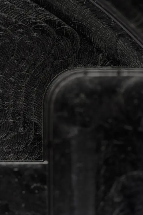
A mirror finish surface is easier to eject from the core since there is very little friction. However, a minimum of 0.5 degrees draft angle is still required for every injection molding part, whatever the finish, to avoid scraping. With textured surfaces, it’s a different story. The deeper the texture goes, the more of an angle you need to add to ensure successful ejection. Rough textures might require a draft angle of 10 degrees or higher. As a rule of thumb, for every 0.1mm depth of texture, an additional 0.4-degree draft angle is recommended.
Ejector mechanism
A sufficient draft angle would ensure easy ejection of the part from the mold, simplifying the ejector mechanism (sleeves, pins, plates) and minimize the chance of the part warping and potentially even decrease the cycle time of the component.
Transcript of remodeling:
So, here is a relatively simple injection molding part that currently lacks draft angles.
You can tell here it’s 90 degrees.
Same for the outside…
And you can visually check by sectioning it.
And if you check over here…you can see that those 2 are parallel.
One way to check is just to see if there is a difference in the angle.
In this case, it shows a distance, which means they are parallel.
Now let’s add a draft angle.
You click the reference surface and then the faces.
In this case, I will select both.
And then I add a draft angle of 1.5 degrees because that texture would dictate the angle.
Not done yet. We should also do the same operation for the outside.
Let’s say we have a different texture. Let’s say it can be something smoother so we don’t need a different angle and 1 degree should suffice.
And here we section it again and take a look at one side.
You can tell that this is not exactly perpendicular to the reference surface.
And neither is the inside cavity.
One more check to see if it tells a different distance for the angle between here and here.
We get an angle of 3 degrees. Two times 1.5.
And it’s the same for the outside: a 2-degree angle
And that’s it.
Closing thoughts and further reading
That was it for our episode on draft angles. If you have questions or remarks, please put them in the comments below. Also, if you have any suggestions on what design aspect to cover next, let us know. We hope you enjoyed this video and that you learned something new. If you did, please give this video a thumbs up and subscribe to the channel. That way you won’t miss out on any future content. See you in the next episode!
Learn more about the importance of draft angles in this article →
