CNC: How to design quality parts for CNC machining (tips & tricks)
Knowing how to properly design parts for CNC machining can save you a lot of time and money. However, a challenge that frequently comes up while designing a part for CNC machining is that no specific industry-wide standards exist. But not to worry, there are recommended design rules and feasible values for the most common features encountered in CNC machined parts. And today, you’re going to be learning all about those!
Hi, my name is Nico and welcome back to another episode in our series: What is CNC machining? In this video you’ll learn all you need to know to design parts optimized for CNC machining. From design restrictions to actionable design rules. Let’s go!
Design restrictions for CNC machining
In order to know how to properly design parts for CNC machining it’s important we have a clear understanding of the different design restrictions in CNC machining. These restrictions are a natural result of the mechanics of the cutting process, and in particular: tool geometry, tool access, workpiece stiffness, tool stiffness and workholding.
Tool geometry
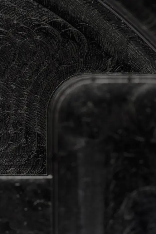
Let’s look at those a little closer and start with tool geometry. Most CNC machining cutting tools have a cylindrical shape with a flat or spherical end, restricting the part geometries that can be produced. Let’s imagine you want the internal corners of your CNC part to have sharp corners. You simply can’t manufacture that. The internal vertical corners of a CNC part will always have a radius, no matter how small of a cutting tool is used.
Tool access
Next, tool access. Surfaces that cannot be reached by the cutting tool, cannot be CNC machined. This prohibits, for example, the fabrication of parts with internal ‘hidden’ geometries, and puts a limit to the maximum depth of an undercut.
Workpiece stiffness
Workpiece stiffness. Because things can get pretty hot during CNC machining and cutting forces are strong, it’s possible for the workpiece to deform or vibrate. This limits, for example, the minimum wall thickness that a CNC machined part can have and the maximum aspect ratio of tall features.
Tool stiffness
Then we have tool stiffness. Like the workpiece, the cutting tool can also deform or vibrate during machining. Because of this, you might end up with looser tolerances and even have tools breaking during manufacturing. (5)This is more prominent when the ratio of length-to-diameter of the cutting tool increases. It’s the reason why deep cavities cannot be easily CNC machined.
Workholding
Finally, workholding. The geometry of a part determines the way it will be held on the CNC machine, and the number of setups required. This has an impact on the cost, but also on the accuracy of a part. For example, when manually repositioning a workholding, this will introduce a small, but not negligible, positional error. This is a key benefit of 5-axis versus 3-axis CNC machining.
Design rules for CNC machining
Alright, we discussed the design restrictions for CNC machining. Now it’s time to learn how to translate these restrictions into actionable design rules. These involve cavities and pockets, internal edges, minimum wall thickness, holes, threads, tall features, small features, tolerances and maximum part sizes.
Cavity depths
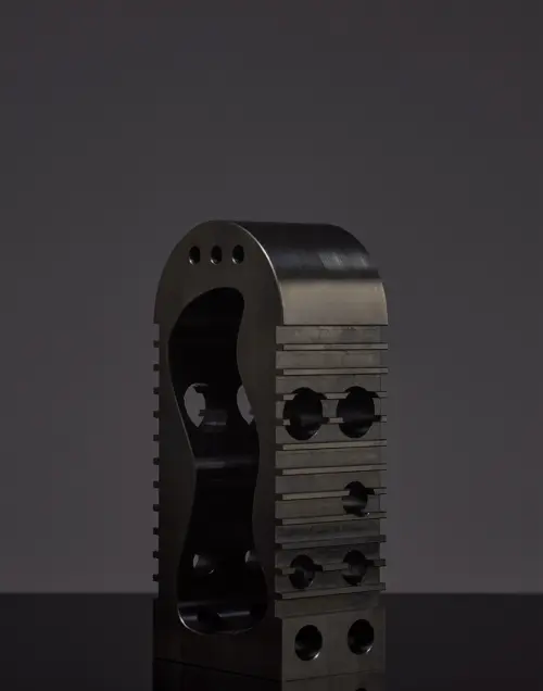
Let’s start with cavity depths. Cavity depths should not exceed 3 to 4 times their diameter. Ten times the tool diameter, or 25 cm, is advisable. Tool deflection, chip evacuation, and vibrations become more prominent when cavities with smaller depth to width ratio. Limiting the depth of the cavity to 4 times its width ensures good results.
Internal edges
Moving on to internal edges. For the vertical corner radius we recommend ⅓ x cavity depth or larger. The larger the fillet, the better. Using the recommended value for internal corner radii ensures that a suitable diameter tool can be used. Increasing the corner radii slightly above the recommended value (for example by 1 mm), allows the tool to cut following a circular path instead of a 90o angle. This is preferred as it results in a higher quality surface finish. If sharp 90 degree internal corners are required, consider adding a T-bone undercut instead of reducing the corner radius. More on undercuts later. Edges on the floor of a cavity should be either sharp or have a 0.1 mm or 1 mm radius.
Thin walls
Next, thin walls. When it comes to minimal wall thickness we recommend 0.8 mm for metals and 1.5 mm for plastics. Usually 0.5 mm for metals and 1.0 mm for plastics is recommended. However, you should evaluate this on a case by case basis. Decreasing wall thickness reduces the stiffness of the material, which in turn increases vibrations during machining and lowers the achievable accuracy. Especially plastics are prone to warping due to residual stresses and softening due to temperature increase. Therefore, a larger minimum wall thickness is advisable.
Hole diameter
For the diameter of holes we recommend standard drill bit sizes. You can find these drill bit sizes in our guide to CNC machining. Link is in the description below. (10) Holes with standard diameter are preferred, as they can be machined with a standard drill bit. The maximum depth of holes we recommend is 4 x the nominal diameter. 10 x the nominal diameter is typical and 40 x the nominal diameter is feasible.
Holes with non-standard diameter must be machined with an end mill tool. In this case, the maximum cavity depth restrictions apply and the recommended maximum depth value should be used. Holes deeper than the typical value are machined using specialized drill bits with a minimum 3 mm diameter. Blind holes machined with a drill have a conical floor (135o angle), while holes machined with an end mill tool will be flat.
Threads
Next up, threads. For thread size we recommend M6 or larger. The minimum size is M2. Choose the largest thread possible, as they are easier to machine. For thread length we recommend 3x the nominal diameter. The minimum is 1.5 x the nominal diameter. The majority of the load applied to a thread is taken by the few first teeth. Threads longer than 3 x the nominal diameter are thus unnecessary. Always design threads as cosmetic in your CAD package and include a technical drawing to your order.
Tall features
Tall features. We recommended max. ratio: height / width < 4. Tall features are difficult to machine accurately, as they are prone to vibrations. Consider the overall geometry of the part: rotating the part by 90° degrees during machining changes the aspect ratio.
Small features
When it comes to small features, tolerances and maximum part size, this is where it gets a little more subjective. For small features, we argue to use 2.5 mm. Features of 0.5 mm are feasible. Cavities and holes down to 2.5 mm (0.1’’) can be CNC machined with standard cutting tools. Anything below this limit is considered micro-machining and must be avoided unless necessary.
Tolerances
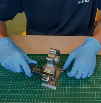
For tolerances, we suggest the tolerance for machining parts to be 0.125 mm. 0.025 mm tolerances are feasible. Tolerances (unilateral, bilateral, interference or geometric) should be defined on all critical features, but never over-tolerance. If no tolerance is specified in the technical drawing, (14)then the standard ± 0.125 mm will be used.
Finally, let’s talk about maximum part size. In CNC milling, we recommend the maximum part size to be 400 x 250 x 150 mm. In CNC turning, we advise, the maximum part size to be Ø 500 mm x 1000 mm. Very large CNC machines can produce parts with dimensions up to 2000 x 800 x 1000 mm ( 78’’ x 32’’ x 40’’). (5-axis CNC machining systems typically have a smaller build volume.)
Undercuts
Last but not least we should talk a little bit about designing for undercuts.
Undercuts are features that cannot be machined with standard tools. It doesn’t matter how the part is rotated, the cutting tools cannot access all surfaces. Therefore, you need special cutting tools: T-shaped, V-shaped or lollipop-shaped tools. How do you design undercuts? We recommend undercut width dimensions to be 3mm(1/8’’) to 40mm(1 ½’’). For the maximum depth we suggest to not go over two times their width. It’s wise to design undercuts with a width of whole millimeter increments or a standard inch fraction. If you don’t use standard dimensions, a custom cutting tool has to be created. Then we have undercut clearance. We recommend a minimum clearance of 4 x the depth of the undercut. For undercuts on internal faces, add enough clearance between the opposing walls to ensure tool access.
Closing thoughts
So there you have it - those are our tips on how to design for CNC machining. I hope everything was clear and that you learned something new today. Any questions? Put them in the comments and we’ll get back to you as soon as possible. Also, give this video a thumbs up if you liked it and subscribe to our channel so you don’t miss out on future episodes. See you next time!
Put your CNC parts into production today.
Get an instant CNC machining quote