carlol
October 17, 2016, 4:28am
1
I had a problem with my board / power overheating (previous post) and have ordered a new board.
I’ve also ordered a relay in order to avoid such a problem in the future.
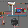
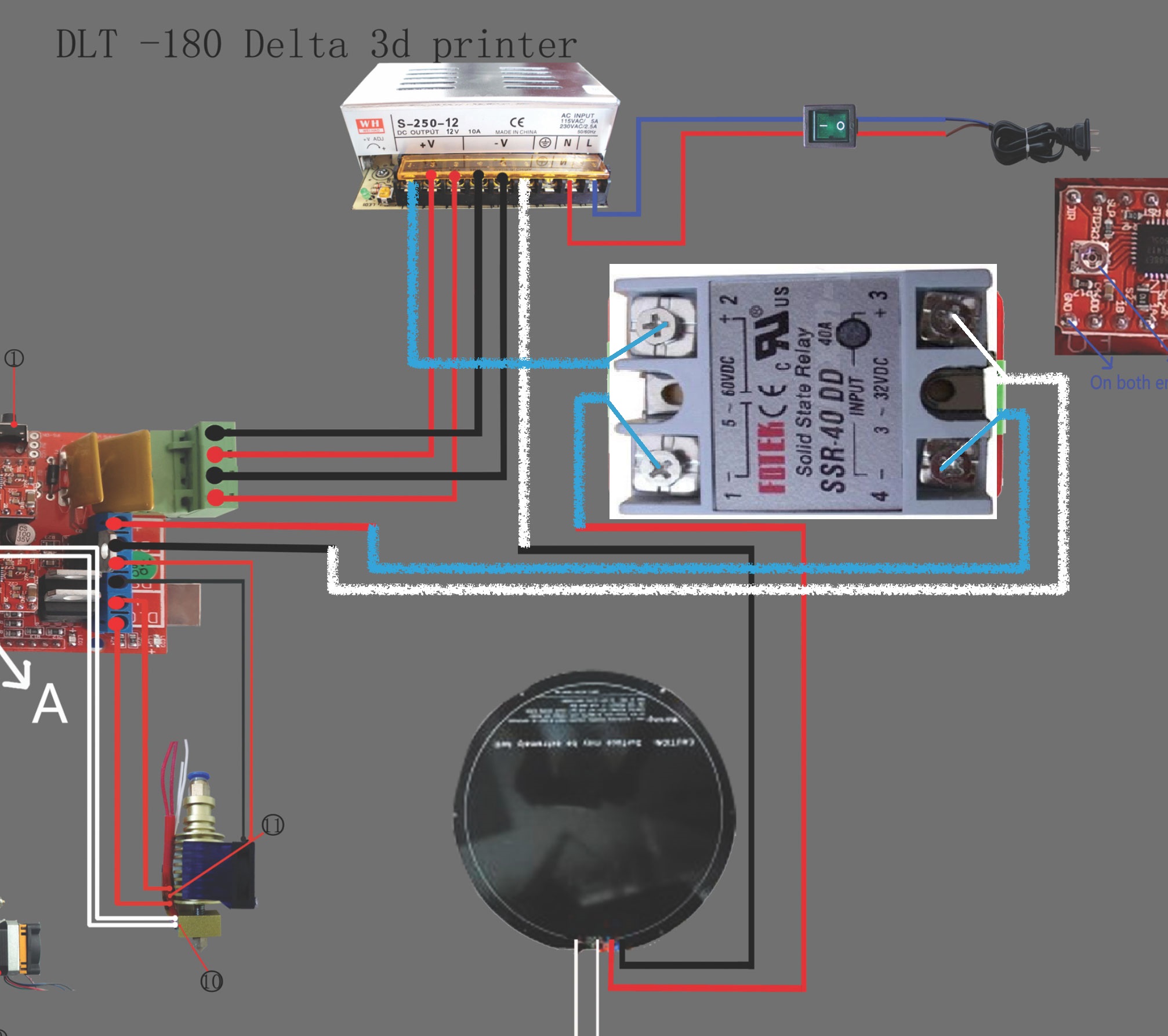
I’ve attached a diagram of how I think this is supposed to be wired.
The relay I ordered is for 10A, but I think the heat bed can pull up to 11A.
So my questions are:
(1) Does this wiring diagram look alright?
(2) Is using a 10A relay OK?
Thanks!
1 Like
Hi,
Please cancel this relay board order!
I would not recommend to use a normal mechanical relay for a DC heabed as it will make a lot of switching with high currents and DC power have the tendency to make arcs so it will kill the relay in a few months (it will look like your melted connector, if not worst…)
Please use SSR (solid state relay) DC-DC type the are really cheap and can handle high currents(40 Amps)
Here is one from ebay:
http://www.ebay.com/itm/New-Solid-State-Relay-SSR-40-DD-DC-DC-40A-3-32VDC-Input-5-60VDC-Output-X5RG-/251656361870?hash=item3a97e3578e:g:lj4AAOSw2GlXIe3w
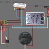
The wiring will look like this for this SSR:
The best solution is to use a silicon heatpad AC type mounted onto a alu plate, use an SSR DC-AC type. This way your power supply doesn’t need output high current, 5-6 amps is totally enough, as the heatedbed runs from AC power just like your power supply. Also the heat up time is dramatically improved with AC power so the heatbed will almost warms the same speed as your print head.
Let me know if you have any questions or something is not clear.
2 Likes
carlol
October 17, 2016, 6:17am
3
Thanks again! @tpalagyi
Have already ordered this SSR.
So the second part of your message means, it would be better to replace the heatbed all together with say this: keenovo heat pad and use a different SSR (such as this: SSR-DA )?
1 Like
Hi,
Great!
The SSR is perfect using the same for a 380x380mm, AC heat pad.
Regarding the silicon heater:
Aliexpress is the cheaper source usually for this. Don’t know your AC voltage (googled it, looks like you have UK plugs and 230V AC system).
Also your current heated bed size is not know for me, but google says it has 160mm round plate.
I made a fast search and found this 200mm:
https://www.aliexpress.com/item/Dia-200mm-300W-220V-w-3M-PSA-NTC-100K-Thermistor-Keenovo-Round-Silicone-Heater-Pad-Delta/32575792674.html?spm=2114.30010308.3.175.fuJm2I&ws_ab_test=searchweb0_0,searchweb201602_2_10065_10056_10068_10055_10054_10069_10059_10078_10079_10073_10017_10080_10070_10082_10081_421_420_10060_10061_10052_10062_10053_10050_10051,searchweb201603_4&btsid=248cd19b-ec10-4f42-8001-dce043805d3b
(Keenovo is the best brand, but didn’t found any difference with the no-name ones). Please note it has 4 wires. 2 for AC power and 2 for the thermistor to measure the temp. (it will connect to your ramps temperature sensor pin just like your current bed)
If it will be too big for your printer look for a smaller one, just look for the 4 wires and mentioning NTC 100k (this is the heatsensor type). Search also with 220v and 230V it will give you different results, but the same stuff.
You will also need a ALU plate 4mm thick to stick this pad under it(it has adhesive tape to already on it), and a 3mm glass recommended on the top of it. Also use some heat shield/insulation under it to increase its performance by radiating heat to print surface direction.
This heat bed upgrade is not a must, but it will works much better.
Let me know your findings if you willing to upgrade, so I can approve it
Regards,
Tamas
1 Like
Ramjet
October 18, 2016, 12:02am
5
OK, Your schematic is fine. Now, the relay is Rated 10A for 30VDC so it is good for up to 300 watts. That is 12.5Amps at 24VDC, So No Problem there.
You may get some arcing on the relay points when it opens (Temp achieved), then more as it will be turning on and off during the print.
That will eventually make it stop connecting, but you can clean the contacts and get more life out of it IF you can open the relay to get to the points.
What is your voltage and what is the resistance of the heat bed? This will tell us what the current will be.
Also, many heaters change resistance as they heat up, No Telling if it will go up or down without knowing what material the heating element is made of.
I doubt you will go over 10 amps tho.
2 Likes
I don’t agree on preferring SSRs over mechanical relays. I have been using a mechanical relay for the heatbeds on two of my machines, and they have both been working fine for over a year. You can get a cheap automotive relay in any automotive shop, for around $10 which will handle 30 amps.
It’s hard to find an SSR with a low ON resistance, and if you get the wrong one then you end up losing lots of power in the SSR - which means your heatbed takes a long time to heat up and possibly won’t reach temperature.
1 Like
carlol
November 1, 2016, 4:27am
7
Thanks all for all of your help.
Final update: I installed the 10A switch first (because the SSR had to ship from China and Japan - I ordered two), with one modification. There was also a signal line (DC+/DC-/IN), so I split the +ve wire from the board to the DC+ and IN). This worked fine.
Then I received the SSR and installed that. One change from @tpalagyi ’s diagram though, I wired the +ve wire from the board to the + 3 on the relay, and the -ve wire to the - 4 on the relay. I’m not sure if it makes any difference, but I just wanted to keep those consistent.
All up and running now. I might give this a shot now and see how it goes before upgrading to a whole new silicon pad setup.
But so far so good, thanks everyone.
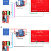
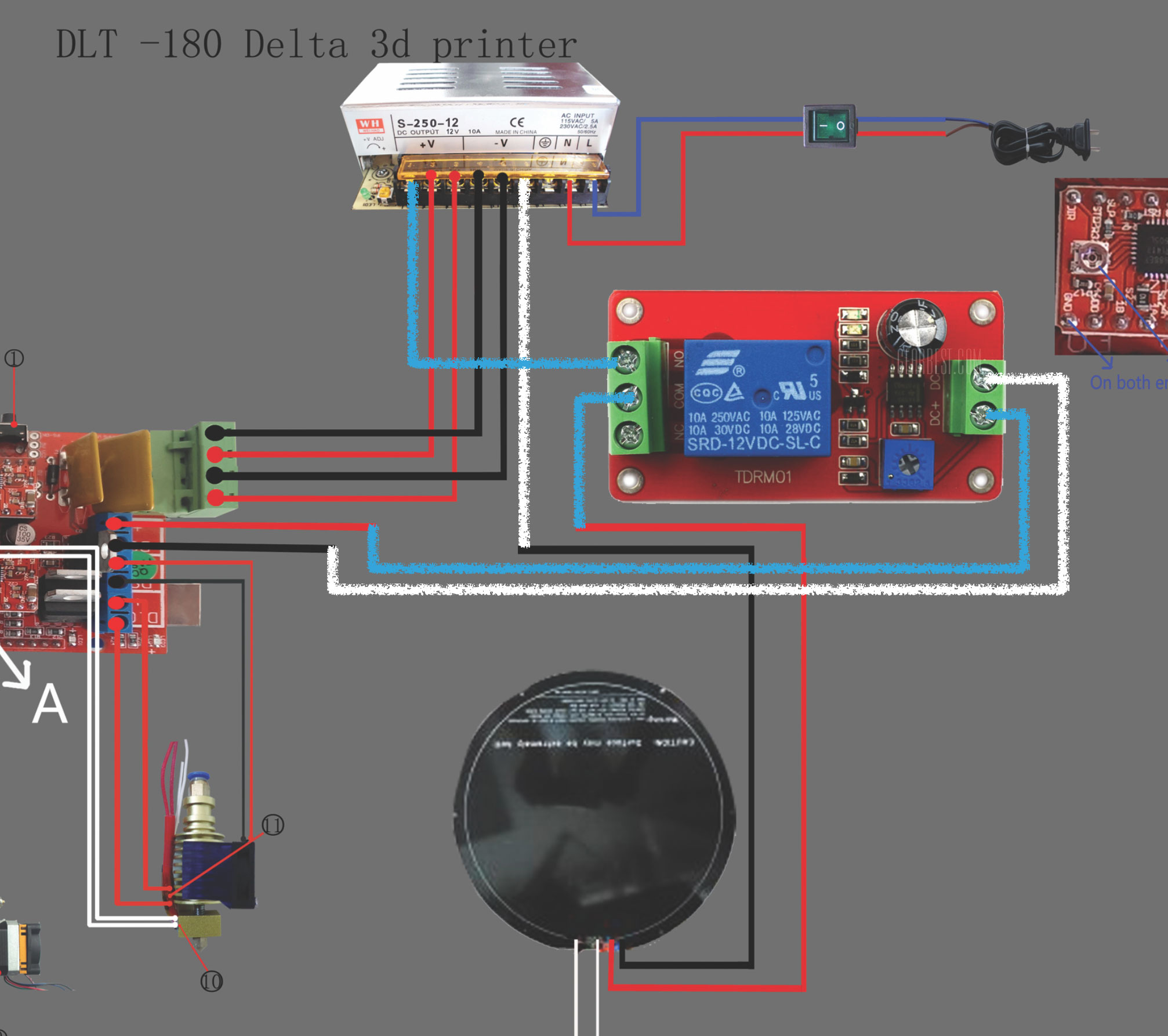
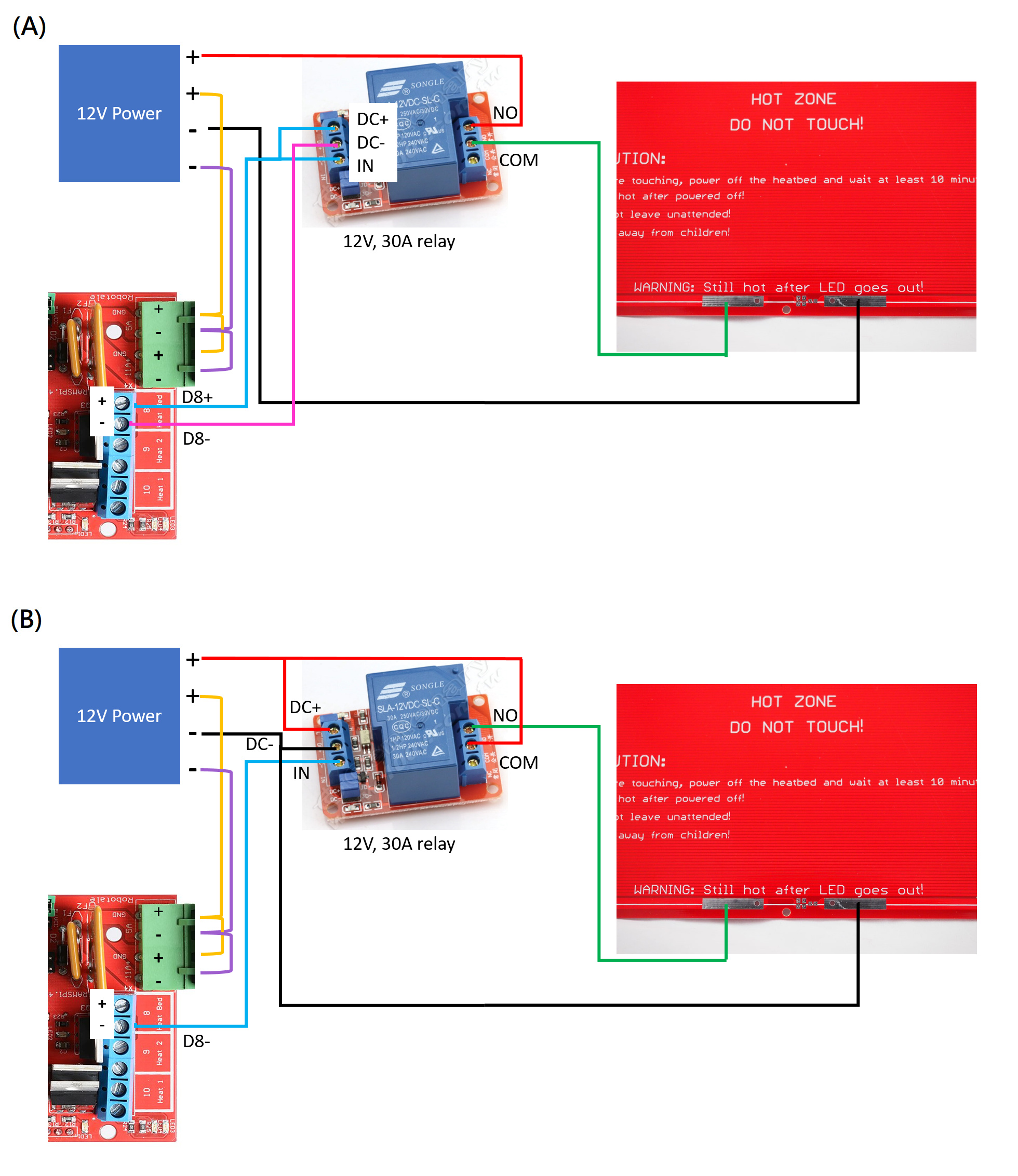
Hello, I bought a 30A relay with six slot (DC+/ DC-/ IN/ NO/ COM/ NC) . So I schemed out the circuit diagram as you said before.
I wired the “+ wire” from the 12V power to the NO slot on the relay, the “+ wire” from the COM slot on the relay to the “+ site” of the heatbed, the “- wire” from the 12V power to the “- site” of heatbed, the “+ wire” from the D8+ slot of RAMPS to the DC+ and IN slot on the relay and the “- wire” from the D8- slot of RAMPS to the DC- slot on the relay. As the picture (A).
Is that right? World it work fine? Because someone tell me that I need to wire the line as the picture (B). I don’t know which one is right. Could you help me please? Thanks a lot!!