20% off your first order. Save up to $1,000/€1,000. Ends 31 Dec 2024. Get a quote

Get instant quote

How do you deal with sharp corners in CNC machining? Designing with the machinist in mind

Have you designed your parts with sharp corners? They may look good on paper, but they're a nightmare to manufacture with CNC machining. In this article, learn how and why to avoid sharp corners in your designs. It'll reduce lead times, cost and potential headaches for machinists.

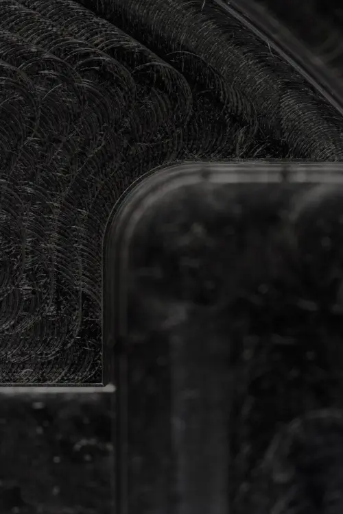
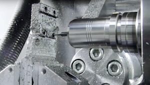
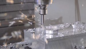
Sharp internal corners are something of a nightmare for CNC machinists. End mills and drills—the two most common CNC machining cutting tools—are cylindrical and have a limited cutting length, and cylindrical tools will always create a radius when cutting an internal pocket.

The geometry of the tool determines the radii on the part. Parts produced using CNC machines will always have at least a small radius, which will make designs with sharp corners much trickier to manufacture. There are methods of machining sharp corners, but they’re quite expensive, so we only recommend keeping them in your design if they're absolutely critical (and worth the extra production costs).

This article explores why sharp corners are challenging for CNC machines and what to do if your design can’t live without them. 


Curious about the cost of machining your designs?

Explore our CNC services Upload a CAD file for a free, instant quote

Why are sharp corners an issue in CNC machining? 

The radius of the tooling a machinist uses during the CNC process will determine what corner radii are possible. It will also directly affect the quality of parts coming off the machine and how long they take to produce. 

Technically, the minimum internal sharp corner radius obtainable with CNC equals the radius of the cutting tool. So, if you’re trying to get a pristinely sharp corner, your tool would need a 90-degree path, and CNC tools aren’t built that way.

If you try this anyway, you’ll need to stop the machine and pivot the workpiece. This will raise the possibility of creating chatter marks from the increased vibration of the tool, slowing down the machining process and resulting in a poorly manufactured part. 

How do you solve the sharp corner problem for CNC machinists?

There are many ways to tackle the sharp corner problem, ranging from adding fillets to switching up the kinds of technologies you use to manufacture your custom parts.

When and how to add a corner radius (or fillet)

The first solution to tackle the internal sharp corners problem is to increase the radius of your part’s corners. Bigger tools produce larger corner radii but run faster, which decreases the time it takes for the part to be machined. However, you may end up with rougher surfaces. 

The depth of pockets is also linked to the tool radius. This is due to the fact that milling with a smaller diameter tool on pockets that are too deep may cause vibrations that result in chatter marks and fatigue on the tool itself. 

As a rule of thumb, the radii at the corners should be at least 1/3 of the depth of the cavity. The cavity's depth should be up to two to three times the cutter's diameter. It’s important to note that while this process is relatively simple, it can be very costly.

When and how to use T-bone and dogbone fillets

When parts need to be assembled, rounded internal corners may cause problems in the fitting. This is where dogbone and T-bone fillets come in handy. 

T-bone fillets

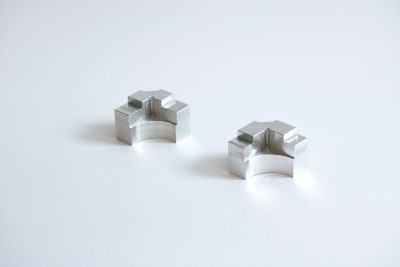
A simple T-bone fillet extends the corner in just one direction. The cutter extends the corner of its tool radius, allowing a mating component to have a sharp corner.

Dogbone fillets

As the name suggests, dog-bone fillets look like canine chew toys.

With dogbone fillets, the corner is extended in two directions, allowing a mating part to perfectly match even if it has a sharp corner. This helps to balance the removed material on either side of the corner, resulting in an overall stronger corner. It’s a simple and viable solution, however, it does remove more material than is necessary.

The most elegant (and least noticeable solution) is to center a two-directional dogbone at a distance √(R² / 2) from the corner itself. This allows the full area occupied by the corner to be machined, without removing an unnecessary amount of material.

When and how to use EDM (electrical discharge machining)

Electrical discharge machining, also known as spark machining or arc machining, is a unique manufacturing process that removes material from a workpiece using a series of recurring electrical discharges. Current flows between two electrodes (separated by a dielectric liquid), which removes material from the workpiece to create specific part dimensions.

There are two different types of EDM:

  • Wire EDM: A thin single-strand metal wire, usually brass, is fed through the workpiece and submerged in a tank of dielectric fluid, typically deionized water. When cutting sharp corners, the wire stays inside the radius, causing a slight overcut.

  • Sinker EDM (or ram EDM): This consists of an electrode and workpiece submerged in an insulating liquid such as oil or other dielectric fluids. The electrode and workpiece are connected to a suitable power supply, which generates an electrical potential between the two parts. As the electrode approaches the workpiece, dielectric breakdown occurs in the fluid, forming a plasma channel for small sparks to jump.

Advantages of EDM:

  • Ability to machine complex shapes

  • Material hardness does not affect the process

  • Internal contours and internal corners down to R0.02 mm

  • No direct contact between the tool and the workpiece, so delicate sections and weak materials can be machined without perceivable distortion

Disadvantages of EDM:

  • The slow rate of material removal

  • Only able to machine conductive materials

  • The additional time and cost used for creating electrodes for ram/sinker EDM

  • Power consumption is high

  • Challenging for machinists and quite expensive

  • Surface texture ends up being quite rough, so post-processing is needed for any area that’s been machined this way

If you're not sure whether the corners in your design will raise any red flags in the DFM process, or want to double-check your parts and drawings before creating a quote, contact networksales@protolabs.com.


Did you know we offer local sourcing for CNC machining?
Upload your design for a free, instant quote

CNC machining, 3D printing and sheet metal fabrication parts
 

More resources for engineers

How do you deal with sharp corners in CNC machining? Designing with the machinist in mind

Read article

What is GD&T? How to reduce manufacturing errors and improve quality

Read article

What is design for manufacturability (DFM)?

Read article

What is anodizing and how does it work?

Read article
cnc-surface finish-as-machined-1

What are the different types of threads for manufacturing? Practical tips for engineers

Read article
Standard Blank Sizes for CNC machining (Sheets & Rods)

Standard blank sizes for CNC machining (sheets & rods)

Read article
Heat treatments for CNC machined parts

What is heat treatment and how does it improve CNC-machined parts?

Read article
Selecting the right CNC material

How do you select the right materials for CNC machining?

Read article
How to prepare a technical drawing for CNC machining

How to prepare a technical drawing for CNC machining

Read article
How to design parts for CNC machining

How to design parts for CNC machining

Read article
Minimizing the cost of CNC parts (13 proven design tips)

14 proven design tips to reduce the cost of CNC machining

Read article

How do you deal with sharp corners in CNC machining? Designing with the machinist in mind

Have you designed your parts with sharp corners? They may look good on paper, but they're a nightmare to manufacture with CNC machining. In this article, learn how and why to avoid sharp corners in your designs. It'll reduce lead times, cost and potential headaches for machinists.

Read article

What is GD&T? How to reduce manufacturing errors and improve quality

What is Geometric Dimensioning and Tolerancing (GD&T) and how is it used? This article explores the basics of how and when to use GD&T to get the best results out of custom part manufacturing.

Read article

What is design for manufacturability (DFM)?

Design for manufacturing (DFM) means taking a design-first approach to manufacturing. In this article, we look at the overall DFM process, the necessary steps for a successful outcome, examples of DFM done right and how to get the most out of your own processes.

Read article

What is anodizing and how does it work?

What is anodizing? Anodizing is key to finishing parts made from aluminum and other metals. Learn how anodizing works and why it is an important part of CNC machining and manufacturing.

Read article
cnc-surface finish-as-machined-1

What are the different types of threads for manufacturing? Practical tips for engineers

What are the different types of threads for manufacturing? In this article, learn how to correctly design threads to reduce lead times and cost for your next CNC machining production run.

Read article
Standard Blank Sizes for CNC machining (Sheets & Rods)

Standard blank sizes for CNC machining (sheets & rods)

Tables of the standard blank sizes (sheets & rods) commonly used in CNC machining.

Read article
Heat treatments for CNC machined parts

What is heat treatment and how does it improve CNC-machined parts?

What are the different types of heat treatment and how do they affect CNC-machined parts? This article explores how heat treatments can be applied to many metal alloys to drastically improve key physical properties like hardness, strength and machinability.

Read article
Selecting the right CNC material

How do you select the right materials for CNC machining?

This comprehensive guide compares the 25 most common materials used in CNC machining and helps you choose the right one for your application.

Read article
How to prepare a technical drawing for CNC machining

How to prepare a technical drawing for CNC machining

How do you prepare technical drawings for CNC machining and why are they important? Technical drawings are widely used in manufacturing to improve the communication of technical requirements between the designer and engineer and the manufacturer.

Read article
How to design parts for CNC machining

How to design parts for CNC machining

In this complete guide to designing for CNC machining, we've compiled basic & advanced design practices and tips to help you achieve the best results for your custom parts.

Read article
Minimizing the cost of CNC parts (13 proven design tips)

14 proven design tips to reduce the cost of CNC machining

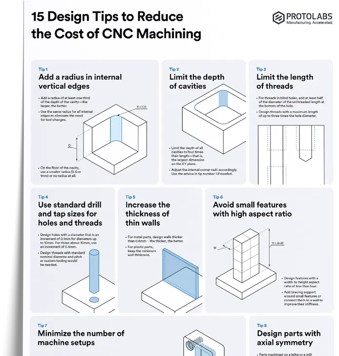
Make the most of CNC machining by optimizing your design and making the right material choices. Read these 14 design tips to help you reduce CNC-machining costs and create the perfect parts for your project.

Read article

Show more

Show less

Ready to transform your CAD file into a custom part? Upload your designs for a free, instant quote.

Get an instant quote