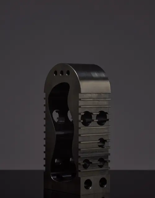
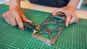
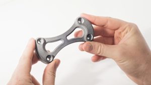
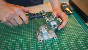
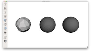
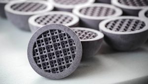
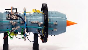
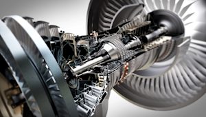
Multi Jet Fusion (MJF) 3D printing uses powdered thermoplastics to quickly and accurately create detailed, durable parts that are suited for industrial manufacturing environments. MJF is frequently used to produce low-volume batches of end-use parts, functional prototypes and parts with organic, complex geometries.
Often compared to selective laser sintering (SLS) and injection molding, MJF is often cheaper and faster than both, making it a viable – if not preferable – alternative, depending on the application, properties and/or batch size.
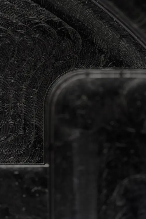
As it’s a relatively new technology, especially when compared to other forms of 3D printing, MJF can only print with nylon powders (such as PA 11 and PA 12), as well as PP and TPU, and produces parts with gray-colored, rough surfaces.
This means you will need to ensure that your application works with the limited materials available to you, and plan to post-process your finished part to ensure a smooth surface or specific color, if necessary.
With all this in mind, let’s explore how MJF works and how to design custom components for the newest form of additive manufacturing.
Curious about the cost of MJF parts?
Our online MJF service Upload a CAD file for a free, instant quote
How does MJF (Multi Jet Fusion) work?
MJF works by using an inkjet array similar to that of a color 2D printer to produce parts. An MJF printer first places a layer of powdered material on a uniformly heated printing bed. An inkjet head then runs across that layer to deposit fusing and detailing agents, then fuses them into a solid layer. This process is repeated, layer by layer, until the final part is ready for use.
The overall process of MJF is quite similar to SLS, with the main difference being the heat source used by each technology. Whereas SLS uses a laser to scan and sinter cross-sections of parts, MJF uses ink from an inkjet head to fuse part layers together.
MJF is capable of creating parts that are more durable and stronger than those created with SLS. Parts made with this process also have sturdy mechanical properties in every geometric direction. MJF can produce finely detailed parts that are chemically resistant to greases, alkalies, oils and aliphatic hydrocarbons.

How do you design parts for MJF manufacturing?
MJF is capable of producing highly detailed and durable components, so it’s often used to manufacture parts or tools such as electronic component housings, mechanical assemblies, enclosures and jigs and fixtures that are fit to withstand industrial environments.
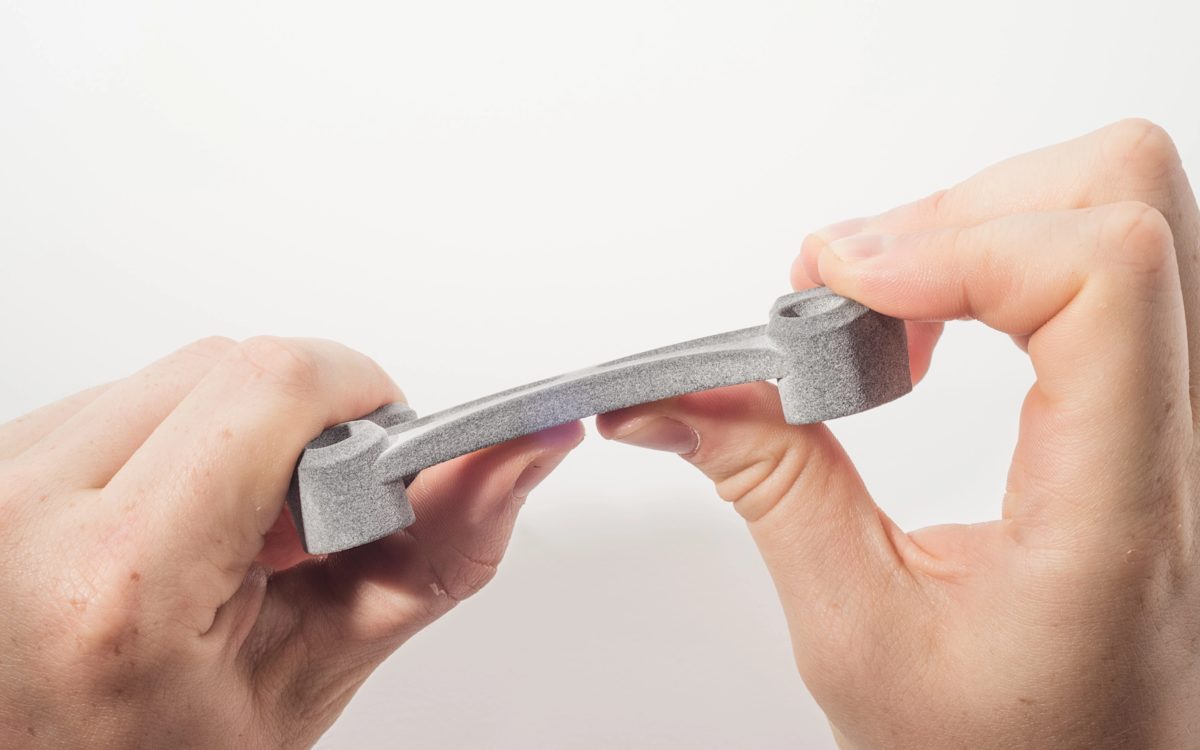
To create such robust parts, MJF uses a small array of impressive materials, including powdered nylon, PP or TPU. Typically, finished MJF parts need to be post-processed. The extent of post-processing always depends on the application, but all MJF-printed parts first need to be cooled (remember to factor that into your expected lead times).
After cooling, it’s good practice to recover unfused powder for later use. This is typically accomplished by vacuuming up the powder in a post-processing station or unit. Powder that remains on the finished part can then be bead-, air-, or water-blasted off, either manually or with post-processing hardware such as an ultrasonic cleaner.
If you are seeking a part with additional properties, you can consider additional post-processing techniques, such as:
-
Dyeing
-
Painting
-
Clear-coating
-
Metallization
-
Hydrographics
-
Protective coatings
What are the best practices for 3D printing with MJF?
The best practices for manufacturing with MJF 3D printing include setting the right print size, choosing an optimal wall thickness, selecting materials based on the desired application and several more design considerations.
If you opt to use MJF to produce custom parts, we recommend a maximum print size of 380 x 285 x 380 mm (14.96 x 11.22 x 14.96 in). The walls of any part created with MJF should be between 2.5 mm (0.098 in) and 12.7 mm (0.5 in) thick.
While MJF is capable of creating small parts or tools with extremely fine details – such as raised text or cosmetic details – we recommend a minimum feature size of 0.5 mm (0.02 in) and print layers that are at least 80 microns thick (0.08 mm).
When embossing, ideally your part will be printed with an upside-down orientation and facing up for engraving. Additionally, parts with curved, hollow geometries can be tricky to achieve with MJF printing, so be sure to adjust your part accordingly or consider a different additive manufacturing process.
Water-resistant parts are also possible when printing with MJF, but only when using PA 12 nylon powder – and in parts that feature walls that are at least 1 mm (0.039 in) thick, or more than 4 mm (0.16 in) for watertight properties.
MJF already enables designers and engineers to produce parts at reduced costs and lead times – especially compared to 3D printing processes such as SLS and injection molding. To get the most out of your MJF print, however, it’s best to keep the above limitations in mind when designing parts. Factor in additional post-processing techniques as well, such as sanding, dyeing or painting, as MJF parts are typically rough and gray-colored.
Other elements of or limitations to MJF to consider include:
-
Warping of long and thin parts. To avoid this, increase part thickness, add ribs in affected areas, replace solid-volume areas with lattice structures (with a 2.5 mm (0.098 in) gap between each lattice) and introduce smooth transitions (ramps instead of steps, for example).
-
Assembly requirements. If parts need to be assembled after printing, leave a minimum gap of 0.6 mm (0.024 in) between areas that will connect. If you are printing parts that are already assembled, a minimum clearance of 0.9 mm (0.039 in) is recommended.
-
Elephant skin. The thicker the part, the higher the chance that a part will improperly cure and feature an uneven pockmarked surface known as “elephant skin.” By decreasing wall thickness or using internal lattices, you can avoid this phenomenon.
Want to learn to design parts for every 3D printing process?
Afterward - a brief history of MJF
MJF was developed by Hewlett Packard (HP) and introduced in 2016, with the claim that it was capable of print speeds up to 10 times faster than other technologies, and could print up to 12,000 voxels per linear inch, per layer. Voxels are the 3D equivalent of pixels on a 2D printer.
This speed and attention to detail, HP said, would enable organizations to create not only functional prototypes but end-use parts fit for hardworking, industrial environments more cheaply and more consistently than ever before.
Frequently asked questions
What are the advantages of MJF?
Multi Jet Fusion (MJF) 3D printing can produce highly detailed, durable and complex parts in less time and at less cost than 3D printing processes such as SLS and injection molding.
What are the disadvantages of MJF?
MJF printers are expensive and unable to create parts with curved or hollow geometries. They also produce rough, gray-colored final parts that may need additional post-processing.
Which industries use MJF?
MJF printing is typically used in industrial manufacturing environments to create functional prototypes or low-volume batches of end-use parts.
Is MJF expensive? How do you cut costs on MJF?
MJF is more expensive than most FDM 3D printing processes but less costly than SLS and injection molding, to which it is most similar.
What are the most common applications of MJF?
Common MJF applications include housing for electrical components, jigs and fixtures for highly specific purposes, and mechanical assemblies or enclosures.
Is MJF a good alternative to injection molding?
Yes, MJF is definitely a viable alternative to injection molding. MJF is similar to injection molding, offering faster lead times and lower costs, but is better suited to low-volume batches.
How quickly does MJF produce parts?
MJF can produce parts as quickly as one day, depending on the complexity or size of the final part.
