Stereolithography (SLA) is a 3D printing process that uses a laser to cure photopolymer resin layer by layer. SLA is best suited for producing small, smooth parts with fine details requiring a high level of accuracy.
This article outlines the SLA printing process, presents the advantages and limitations of designing components to be printed with SLA and discusses the most common SLA materials.
Design better: Download the free " Design rules for 3D printing" poster in high-resolution, full of actionable guidelines for the six major 3D printing processes.
What is the SLA printing process?
The SLA printing process is highly accurate but can be time-consuming. To achieve the best results, a designer should keep part orientation and isotropy in mind.
SLA printing
A typical desktop SLA machine contains a UV laser to cure a specific layer of a component from a tank of photosensitive resin. The bottom of the tank is transparent and the UV laser is precisely controlled to trace a 2D contour of the object. The laser cures the resin, forming a solid layer.
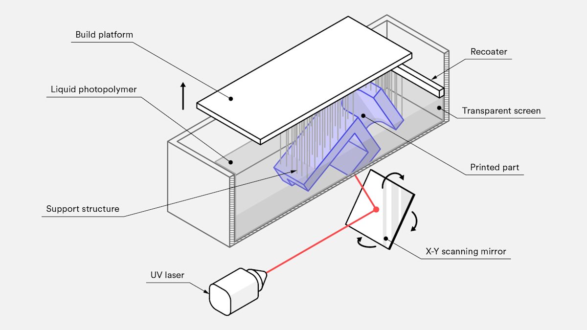
Each pass of the laser creates a very thin slice of the object. This thin slice is stuck to the layer below it (or the build plate) and the tank bottom. The newly printed layer is then separated from the bottom. Depending on the machine, this can involve peeling, sliding or shaking the tank. The build plate then moves down a layer in thickness and the process is repeated again and again until the part is completed.
For a successful SLA print, it is critical to reduce the forces on the newly printed layers during the separation stage. The separation stage creates areas of high stress along what is, in some cases, a razor-thin edge that can cause high failure rate and warping if the part sticks to the tank bottom rather than the build plate.
Print orientation
When orienting a part for SLA, the biggest concern should be the z-axis cross-sectional area. The forces that determine if a print sticks to the tank are directly proportional to the print’s 2D cross-sectional area. This is why the part is printed to the plate at an angle, and support reduction is not a primary concern (as shown in the images below). When you are orienting parts for SLA prints, try to minimize the cross-sectional area along the z-axis.
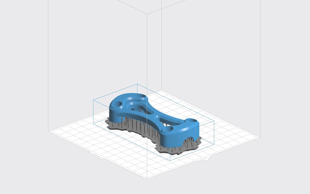

For designers, it is important to understand how and why part orientation impacts the quality of an SLA print. When you need to orient components so that the z-axis cross-sectional area is reduced, it can result in the model requiring a significant amount of added support. In some instances, a design may need so much support that printing in SLA no longer proves cost-effective. Or the necessary support can be so detrimental to the appearance of the part that, once support has been removed, the result is visually unsatisfactory. To optimize a design for SLA, limit the number of horizontal members, hollow out components and reduce the cross-sectional area.
Isotropy
SLA prints are isotropic because the layers chemically bond to one another as they print, resulting in nearly identical physical properties in the x, y and z directions. Whether the part is printed parallel or perpendicular to the build plate, its final material properties are not noticeably impacted.
How do you design for SLA printing?
SLA is best suited for producing small, smooth 3D printed parts with fine details to a high level of accuracy.
Print features
The detail level an SLA printer can produce depends on laser spot size and resin properties. General guidelines for designing for SLA are as follows:
Supported walls
These walls that are connected to other structures on at least two sides (so they have very low likelihood of warping) should be designed at a minimum of 0.4mm thick.
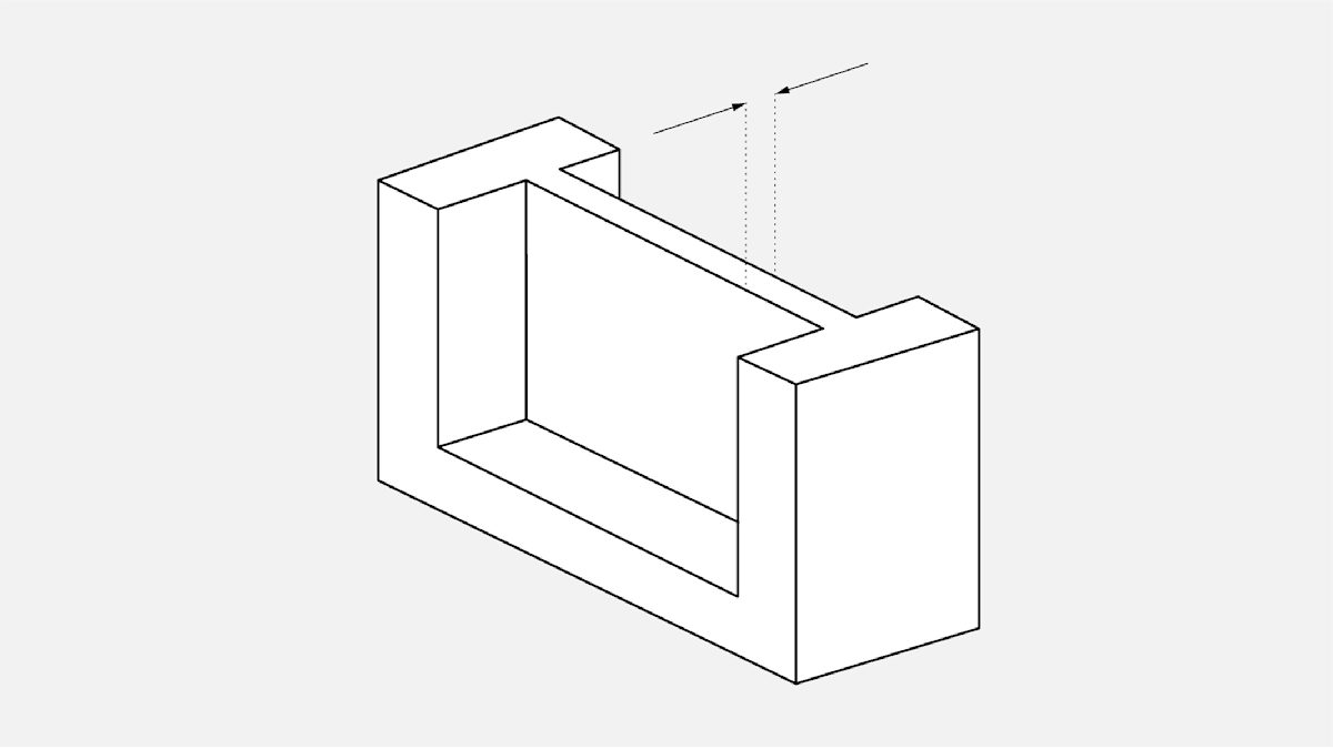
Unsupported walls
Walls that are connected to the rest of the print on less than two sides, and are at a very high chance for warping or detaching from the print. These walls must be at least 0.6 mm thick and should be designed with filleted bases (where the wall connects to the rest of the print) to reduce stress concentrations along the joint.
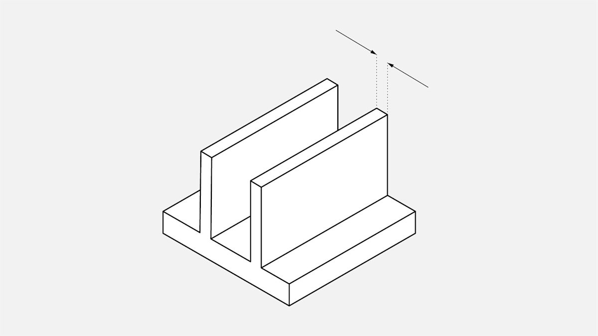
Overhangs:
Unless the model is being printed without adequate internal and external support structures, overhangs pose very little issue with SLA printing. Printing without supports often leads to warping of the print, but if it is necessary to print without supports, any unsupported overhangs must be kept less than 1.0mm in length and at least 19° from level.
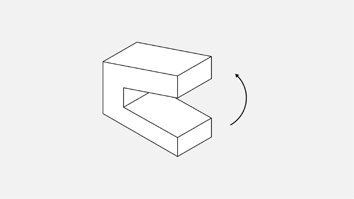
Embossed details (including text):
These features on the model, which are raised slightly above the surfaces around them, must be at least 0.1mm in height above the surface of the print to ensure the details are visible.
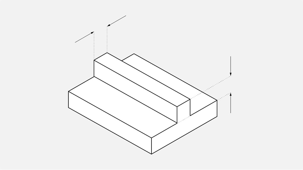
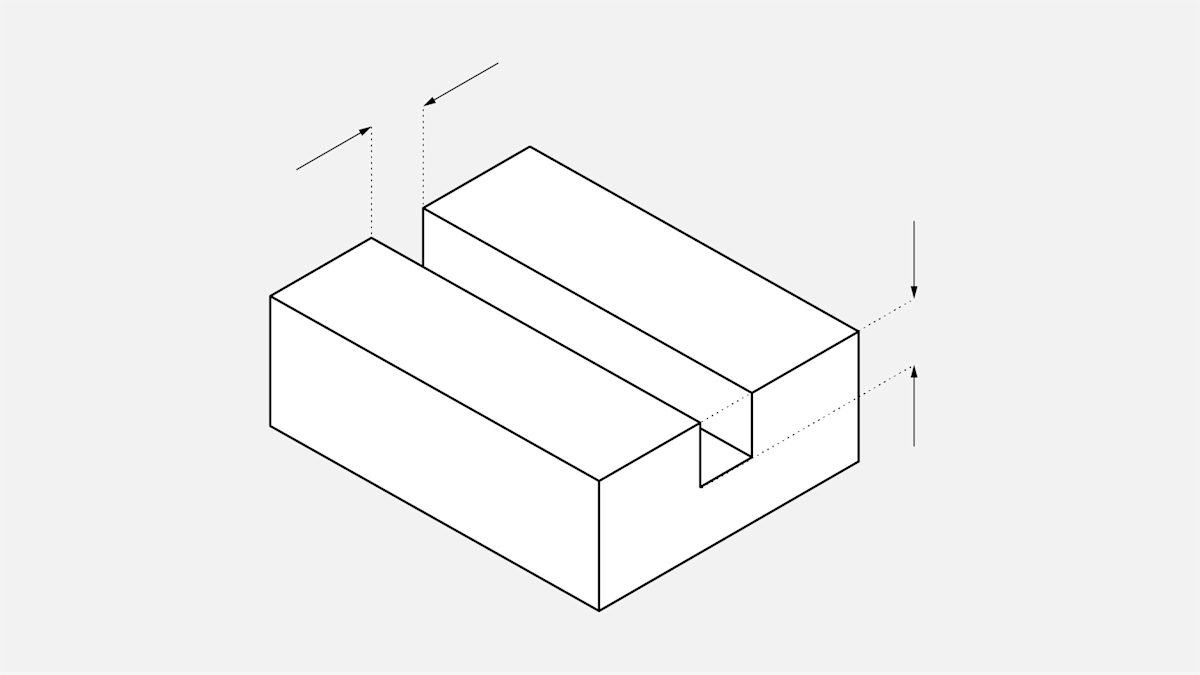
Engraved details (including text):
If too small, these features, which are imprinted or recessed into the model, are at risk of fusing with the rest of the model during printing. The details must therefore be at least 0.4mm wide and 0.4mm thick (in terms of the distance from model surface to recessed detail).
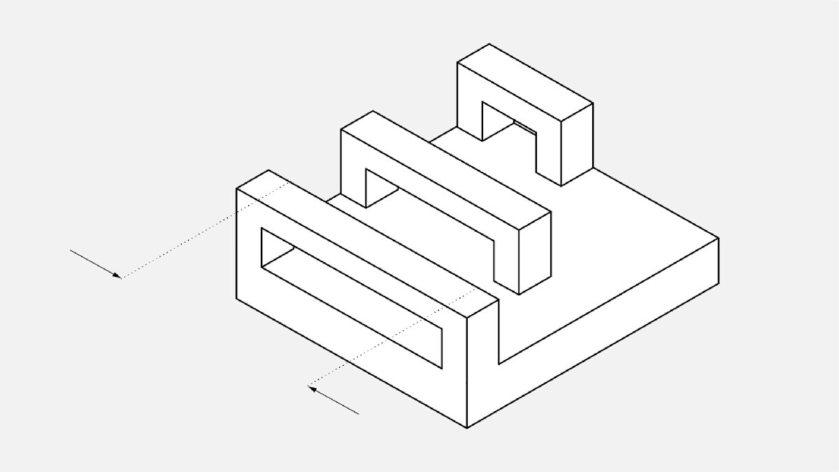
Horizontal bridges:
These bridges between two points on a model can be successfully printed, but the wider horizontal bridges must be kept shorter (less than 21mm) than thin bridges. Wider bridges have a greater z-axis area of contact, increasing the chance of print failure during peeling.
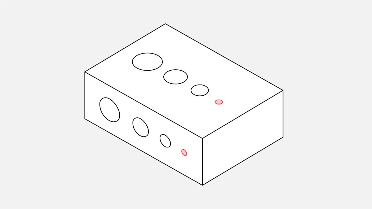
Holes:
If their diameter is less than 0.8mm in the x-, y- and z-axes, holes may close off during printing.
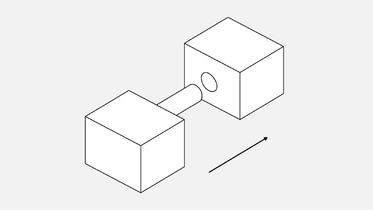
Connections:
Use 0.5mm clearance between moving parts.
Use 0.2mm clearance for assembly connections.
Use 0.1mm clearance to give a push or snug fit.
Resolution
SLA can achieve much higher resolutions than FDM because it uses a laser to solidify the material. SLA printing resolution in the xy-direction (or horizontal resolution) depends on the laser spot size, and can range anywhere from 30 to 140 microns. This is not an adjustable printing parameter, as the minimum feature size cannot be smaller than the laser spot size.
Resolution in the z-direction (or vertical resolution) varies from 25 to 200 microns. Choosing vertical resolution involves a trade-off between speed and quality. For a part that has few curves or fine details, a print at 25 microns versus a print at 100 microns shows little visual difference. By comparison, a desktop FDM machine typically prints z-axis layers at 150 to 400 microns.
Hollowing and cupping
SLA machines print a solid, dense model. However, if the print is not intended to be a functional part, hollowing the model significantly reduces the amount of necessary material and print time. To reduce the risk of failure during printing, keep the walls of the hollowed print at least 2mm thick.
When 3D printing a hollow part, add drainage holes to prevent uncured resin from getting trapped inside the final print. Uncured resin creates pressure imbalances within the hollow chamber, causing what is known as cupping. Small failures, such as cracks or holes, spread throughout the part, causing complete failure or part explosion if uncorrected. Drain holes should be at least 3.5mm in diameter. At least one hole must be included per hollow section.
What materials do you use for SLA 3D printing?
This table describes common SLA resins.
| Resin type | Description | Application |
|---|---|---|
| Standard resin | Most commonly used for general printing and can offer high detail surface finishes with resolutions smaller than 25 microns. These resins offer no special material properties and are typically more brittle than standard FDM materials. | Ideal for high detail prototyping or models that are not functional. |
| Engineering resins | SLA resin manufacturers more recently have been pushing into the engineering sector by simulating common engineering plastics offering ABS or polypropylene-like, flexible and high temperature resins. These resins offer superior engineering properties without sacrificing print quality but come at a higher cost. | Tough, flexible and high temperature applications. |
| Dental Resins | For general orthodontics, general purpose resins or castable resins are commonly employed. Recent releases of Class 1 and 2 biocompatible resin over the last year also now allows for use of SLA technology to create surgical guides. These resins highly precise and are durable enough to be sterilized via autoclaving prior to surgical use. | Dental applications |
| Castable Resins | These resins specialize in fine detail and delicate feature printing and have been designed to allow for direct investment casting. Very small details captured by this resin with a minimum feature size of 0.2 mm. When properly cured the resin burns out with little to no ash or residue. | Jewellery, fine detail models and investment casting applications |
Designing for SLA post-processing
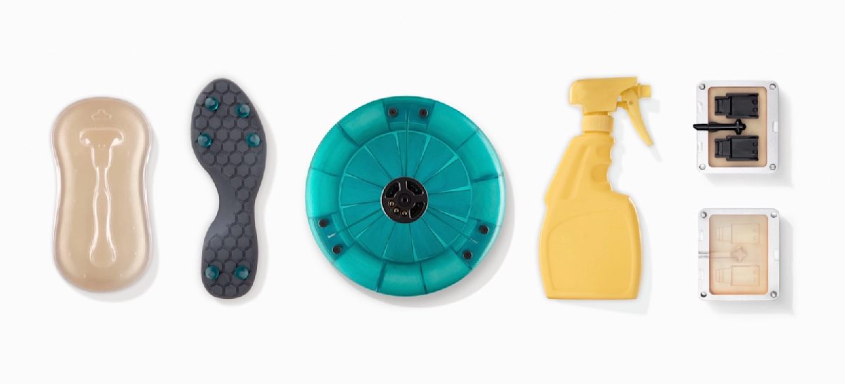
A range of surface finishes can be achieved on SLA-printed parts. The desired surface finish is often governed by cost and application. Read this detailed guide on the most common SLA surface finishes.
What are the limitations of SLA 3D printing?
For all its capabilities, SLA 3D printing also has constraints. These include the printers’ smaller build volumes, higher costs, and the brittle nature of materials used.
Print volume
SLA printers generally have a much smaller build volume than most FDM printers, with the exception of commercial machines. The Formlabs Form 2 (a common desktop SLA printer) has a build volume of 145mm × 145mm × 175mm while the Ultimaker 2+ (a common FDM desktop printer) offers 223mm × 223mm × 205mm. When SLA print geometries exceed the printer capacity, they can be printed in smaller sections and then assembled. The best method for bonding SLA-printed components together is a five- to 30-minute epoxy.
SLA versus FDM costs
The cost by volume of SLA resin is higher than the filament used for FDM printing. SLA prints are therefore usually more expensive. However, SLA can be used to print intricate details, which makes it a competitive option compared to many of the more industrial 3D printing technologies.
Cost comparison: A liter of standard SLA resin typically costs around USD$150 while a 1-kilogram roll of ABS filament for FDM costs around USD$25.
Material properties
SLA 3D printed parts are generally not suitable for producing functional parts that can withstand subjected to loads. The nature of SLA resins means that parts are brittle, less stable than other 3D-printed materials over long periods and inclined to experience some creep. Most SLA-printed parts require curing in a UV chamber post-print. Post-curing enables parts to reach their highest possible strength and become more stable.
What are the best design practices for SLA?
-
SLA is ideal for small parts that require a smooth surface finish—as compared to injection molding—and a high level of accuracy.
-
Support structures are critical for successfully printing accurate SLA parts. If a good finish is required on a surface, the part should be oriented so that the surface does not contact support material, thus typically upward facing.
-
SLA parts typically have poor mechanical properties and are best suited for non-functional prototyping, enclosures and visual models.
What are the design specifications for SLA 3D printing?
| Feature | Design specifications |
|---|---|
| Supported walls | At least 0.4mm thick |
| Unsupported walls | At least 0.6mm thick |
| Overhangs | Less than 1.0mm in length and at least 19° from level |
| Embossed details | At least 0.1mm in height |
| Engraved details | At least 0.4mm wide and 0.4mm thick |
| Connections | 0.2mm for assembly connections and 0.1mm for snug fit |
| Holes | Minimum diameter of 0.5mm |
Want to learn more about 3D printing? Read our full guide: What is 3D printing?
