Introduction
This is a continuation of the previous tutorial on 3D modeling an enclosure, in the article the two buttons and the two-part housing were created. Follow the 3D modeling enclosures guide, or download the Fusion 360 enclosure file to follow along from here.
This guide demonstrates 3D modeling techniques for creating functional living hinges. Fusion 360 has been used to model these parts but most CAD packages are very similar in operation. If you don’t currently have Fusion you can download a free copy for hobbyist use here.
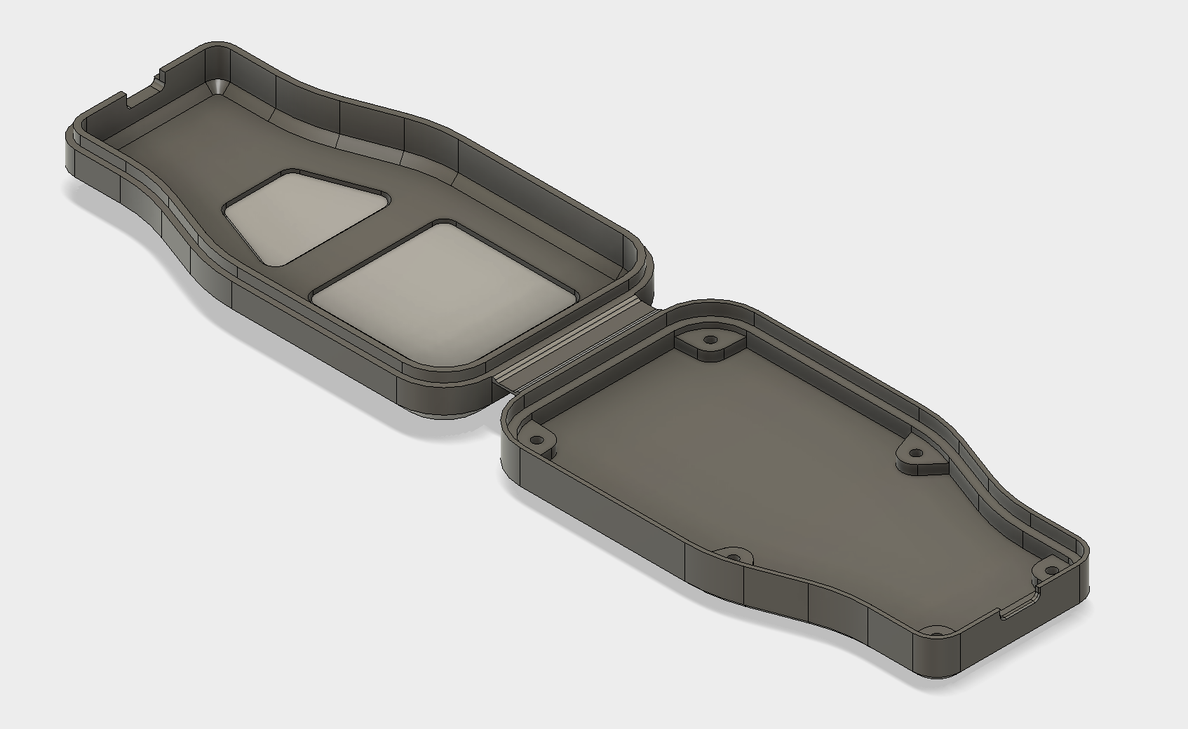 Enclosure with completed living hinge.
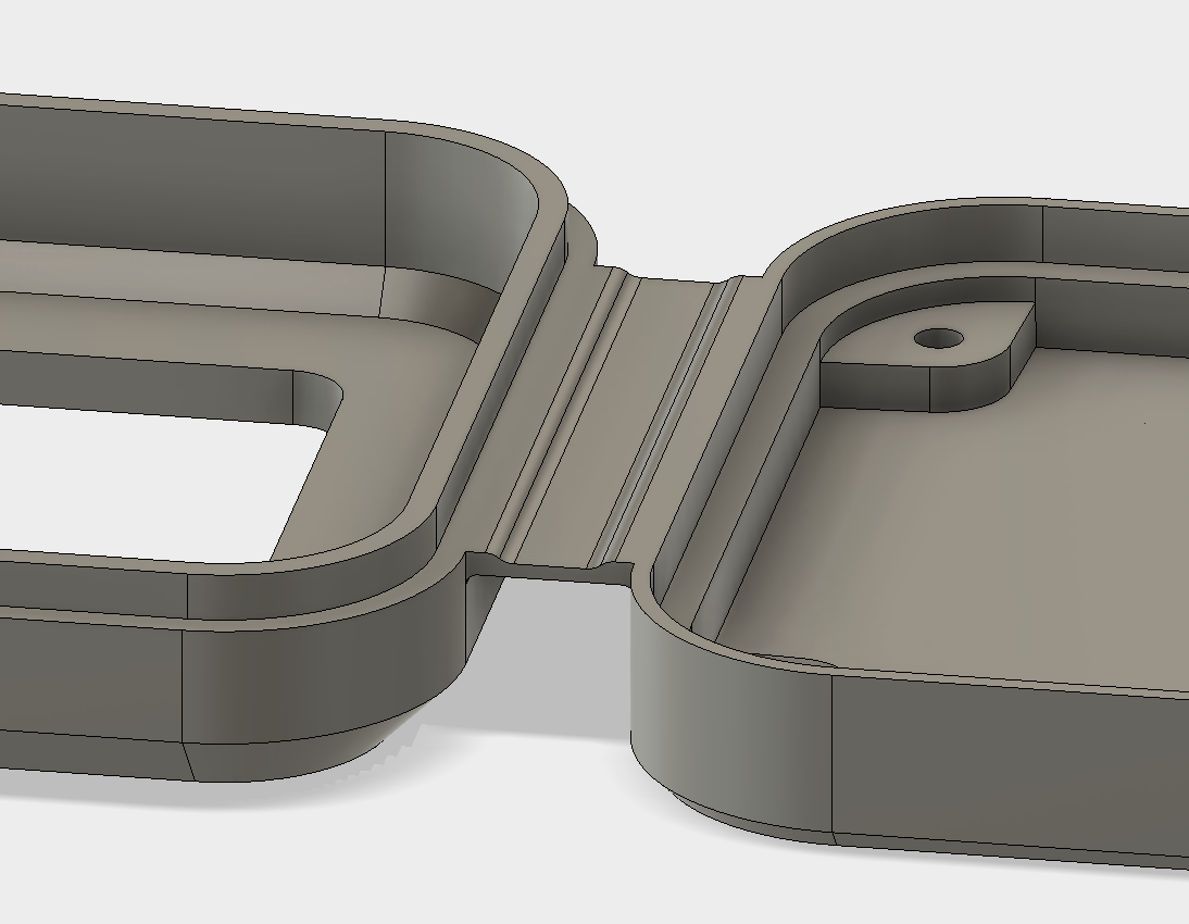 Close-up view of completed living hinge.
Part 1 - Positioning
The first stage is to position both halves of the enclosure so they can be printed easily and with a good surface finish. It is important to ensure both bottom faces are on the same plane. This eliminates the need for support material which also results in a poor surface finish after removal.
 Poorly positioned enclosure parts, left side requiring support material to print correctly.
 Parts positioned to eliminate the need for support material, resulting in a much better surface finish.
The Move tool can be used to position the top half of the case to the correct position ready for the living hinge to be added. The enclosure buttons are also selected to ensure they are moved into the correct position with the half of the case.
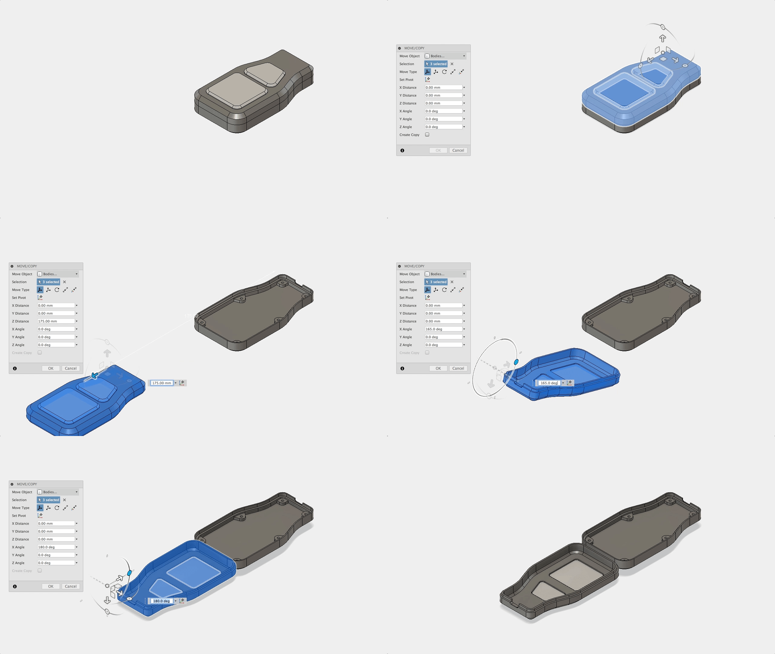 Moving the top half of the enclosure and the buttons into position.
 Both case parts in final position.
A gap of 7mm has been tested to give good results, however experimentation will ensure the optimal distance for a specific enclosure. A distance below 5mm is not recommended due to a very small bend radius, creating more intense stress during movement. This dimension was based on standard injection mold dimensions and the Protolabs Network Living Hinge KB article.
Part 2 - Hinge Sketch
The next stage is to create the sketch required to extrude the living hinge. If the enclosure was modeled centrally from the origin the origin work plane can be used. If this plane is not in the middle of the part it is possible to use a Midplane to construct the sketch. The Midplane tool is selected from the Construct menu and two faces are selected, this will create a new workplane at the midpoint of the selected faces.
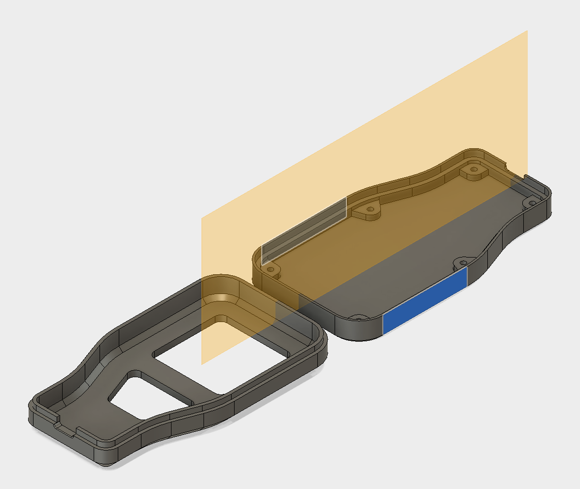 Two selected edges and the midpoint construction plane.
The sketch can now be created on this plane, referencing the edges of the case parts using a coincident constraint. This will ensure the sketch is automatically updated if either of the case parts are moved. After testing a few different variations on geometry and dimensions of the living hinge the most effective was found to be a 1mm section, tapering down to 0.6mm for the main hinge.
This gives good strength at the sides and controls where the hinge will bend. As a hinge is closed the outer surface is placed under tension while the inner surface is compressed. This stretches the outer surface of the hinge. To account for this, a good living hinge design has a long curve length on the outer surface and a short inner surface.
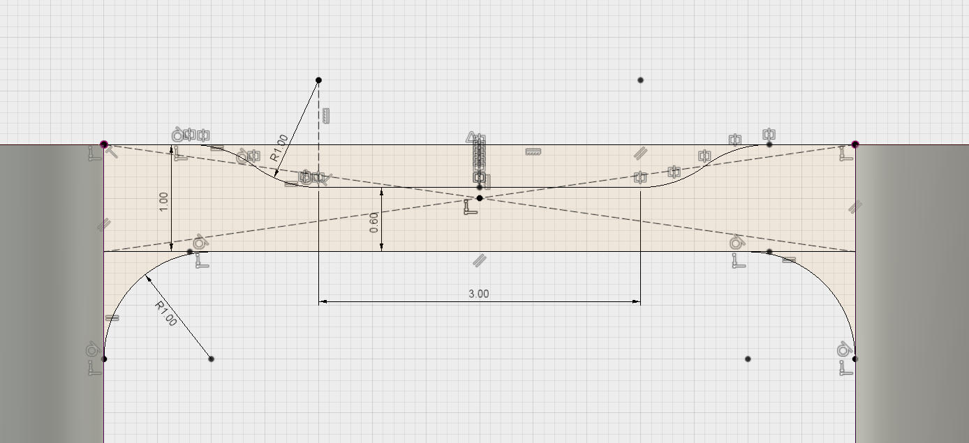 Recommended sketch geometry and dimensions for this part.
Part 3 - Extruding Hinge
The sketch is now complete and can be extruded to form the body of the living hinge. A Symmetric direction is chosen to ensure the hinge is evenly distributed along the edge of the case. A Join operation was used to enable the case to be printed as a single part.
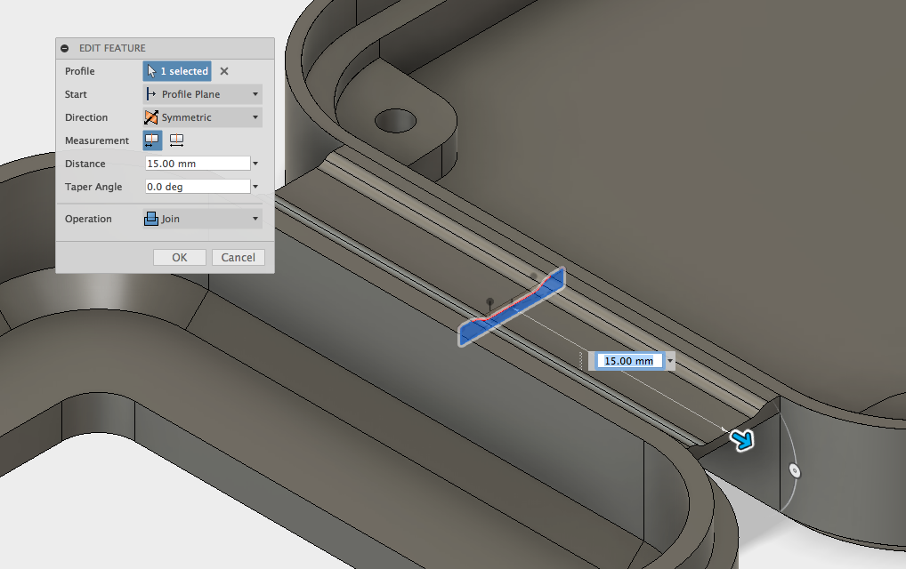 Sketch profile being extruded to create the living hinge.
The living hinge feature is now complete, for more information on living hinge design you can refer to this article.
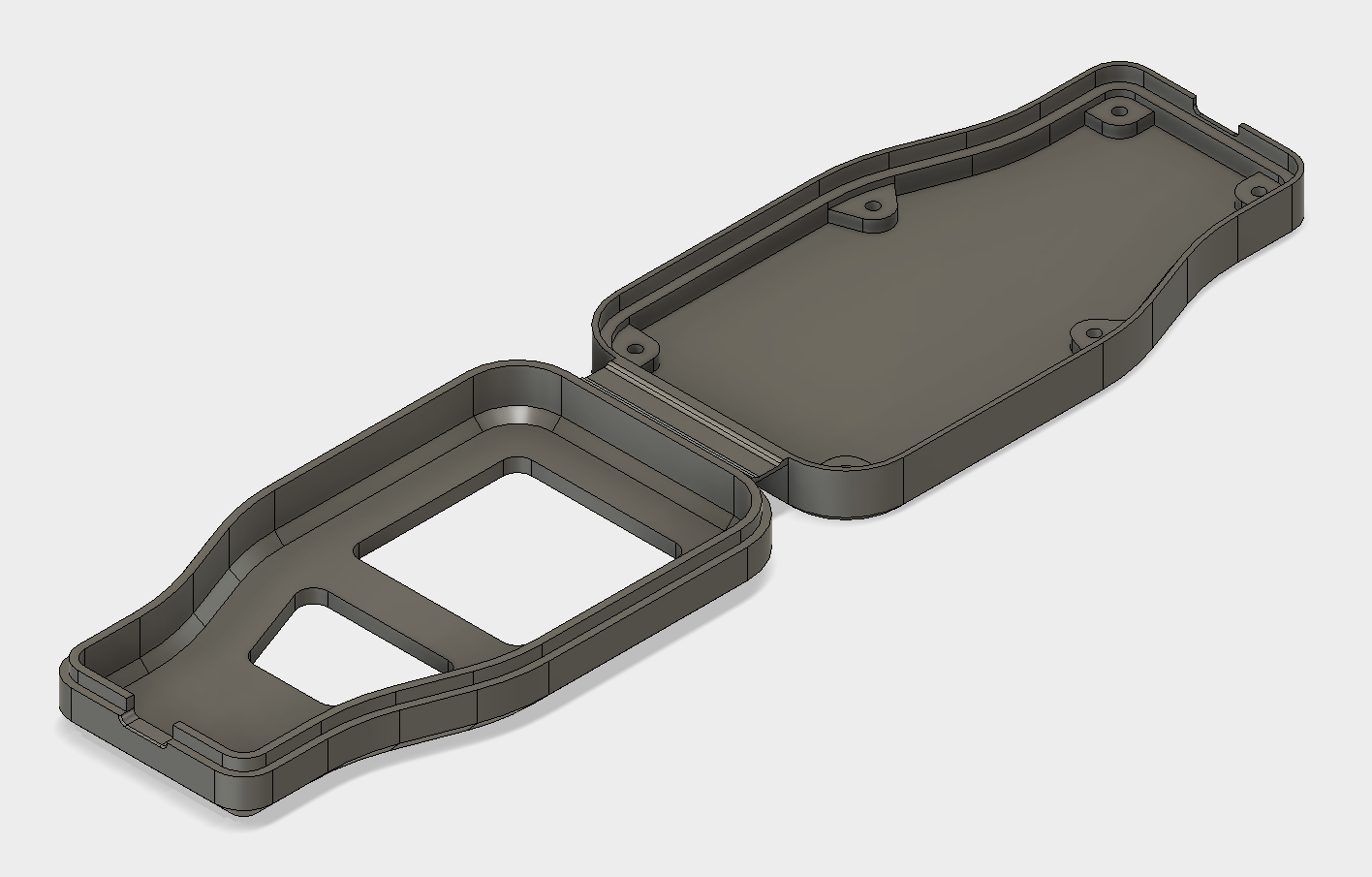 Completed living hinge part.
Learn more from our in-depth 3D printing guide here.
